ARM1 A/F Meter Installation in the
Mitsubishi 3000GT/Dodge Stealth
by Jeff Lucius
Introduction
These instructions will help you connect your Split Second ARM1 A/F meter to the correct wires on the connector at the Engine Control Module (ECM). The connections should be similar for A/F meters from other manufacturers. There will be one or two ground wires, a power wire (for ignition-switched +12 V), a wire for the O2 sensor, and probably a wire for lighting. I think it is a good idea to use the power and ground wires at the ECM connector if the device is tapping into any other ECM wire, such as an O2 sensor wire in this case. The light wire by necessity must tap into another source. I use the dash lights rheostat switch connector for this (see the middle of my web page on removing the instrument panel for details, 2-dashpanel.htm).

The tools and supplies needed include: Phillips and flat-head screwdrivers, 10-mm socket and driver, some male and female disconnect terminals (insulated spade type) sized for 18-20 gauge wire, a wire cutter/stripper/crimper tool, some snap-splice connectors (see picture below) or other type of similar connector, some insulated 18-gauge, multi-strand wire, a few cable ties, electrical tape, and a volt-ohm meter. Alternatively, you could solder the wire connections then wrap them or maybe use shrink tube.
After I installed the ARM1 (and the ARC2 and S-AFCII, which also tapped into the ECU wires) I became aware of a very handy patch harness built by Autosport Wiring specifically for our cars (and many others). They want $139 for 1990-1993 ECUs and $159 for 1994-1998 ECUs. The patch harness plugs between the ECU and the factory harness. All taps can be made into this patch harness and so the car can be returned quickly to original condition or the patch harness modified for other equipment. Pretty neat, if a bit expensive. For some harnesses Autosport Wiring has highlighted some commonly tapped wires like RPM, TPS, injector 1, etc. If you decide to use one of these handy harnesses, the instructions below can still be followed, except you will be working on the patch harness rather than the factory harness.
These instructions are specifically for the 1992 3000GT/Stealth DOHC Turbo ECM. My web page 2-ecu94.htm reproduces the pages from the service manuals describing the ECM connectors for all models. The power, ground, and O2 sensor pins/wires for DOHC models are summarized in the table below.
| Some ECM Terminals for DOHC Turbo Models |
| Function |
1991-1993 |
1994-1995 |
1996-1997 |
1998-1999 |
| Front O2 sensor |
55 |
75 |
75 |
72 |
| Rear O2 sensor |
56 |
76 |
76 |
71 |
| IG power (+12V) |
62 |
82 |
82 |
99 |
| Ground |
13 or 26 |
13 or 26 |
13 or 26 |
46 or 58 |
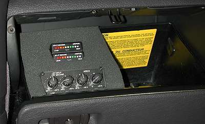
You can decide where to best mount your A/F meter. Because A/F meters are warning devices as well as tuning devices, I have a meter for each O2 sensor. In the models that use upstream and downstream sensors (before and after the pre-cats respectively), it is the upstream, or "front", sensor that is tapped. My A/F meters are mounted in the glovebox.
Getting to the ECM
1. Driver seat. Move the driver's seat as far back as it will go.
2. Battery. Disconnect the negative battery terminal. Be sure you have security codes if any devices need them.
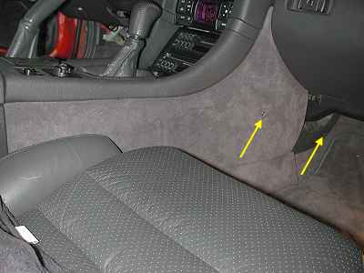
3. Left side floor console cover. Pry out the plastic plug near the front of carpeted cover. Pry open the cap on the screw in the middle of the cover. Remove the screw. Start at the front of the cover and pull out and down.
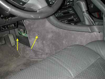
4. Right side floor console cover. Pry out the plastic plug near the front of carpeted cover. Pry open the cap on the screw in the middle of the cover. Remove the screw. Start at the front of the cover and pull out and down. Then you will have to slide the panel forward to slide it off a connector near the back of the panel.
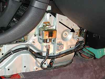
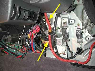
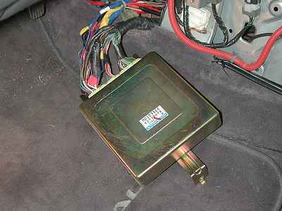
5. Engine Control Module. The ECM is retained by two bolts on the left side and one bolt on the right side. On the driver's side you may need to move a piece of the harness first to get good access to the bolts. After removing the three 10-mm bolts, slide the ECM out for easy access to the connectors. If you need to test the ECM or one of its wires, then do not unbolt the ECM. Leave it in place and tap the wires with an analog or digital voltmeter (look at the service manual for which to use for which wires) by prying open the access covers on the back of the connectors.
Tapping into the ECM Wires
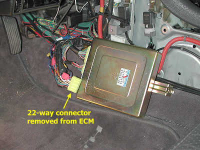
1. Disconnect ECM connector. Be sure to ground yourself before working with the ECM. Just touch some metal part on the car like part of the body or the metal frame of the floor console. Press down on the release arm in the middle of the 22-way connector and slide the connector away from the ECM.
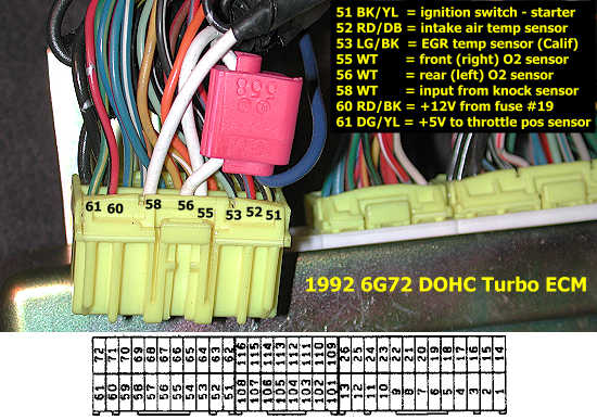
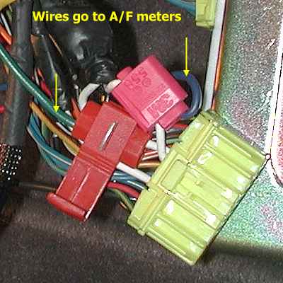
2. Identify the wires. Split Second has a data sheet about the ARM1 this link: http://www.splitsec.com/products/arm1/arm1ds.htm. I have the PDF version of this data sheet available here: misc/ss-arm1.pdf (you will need the Adobe Acrobat Reader for this file). The ARM1 has 5 wires that need to be connected. The way I have done this is different than what Split Second describes. I connected the black and brown ground wires together and tapped them into an ECM wire. I used pin 72 (ground wire for the throttle position sensor) but pins 13 or 26 may be better choices. The red wire tapped ECM pin 62, which is positive 12 volts active only when the ignition switch (IG1) is on. The orange wire went to one of the O2 wires (55 or 56) on the ECM as shown in the picture below. Please note that you should not go by wire color alone on the ECM connector. There are three white wires in the picture below. Be sure to identify the number and position of the terminal on the ECM connector.
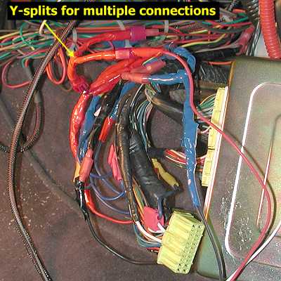
3. Make the connections. It is a good idea to draw a plan of the connections on a piece of paper. Below is an example (a freehand drawing is fine, of course). Include the color of the wires from the device, what the wires are for, the ECM terminal number they attach to, and the type of connector for the end of the wire (male or female disconnect, splice, etc.). The wiring plan will help you make up pieces of the new "mini-harness" to connect the ARM1. You may want to consider including making extra connections available on the switched 12-volt and ground wires for other devices that can tap into ECM wires, such as the ARC2, VPC, AFC, and similar devices. The "Y" pieces in the figure below provide for this. I already had an ARC2 and one ARM1 wired in when I added this second ARM1 and took these pictures. I recommend not splicing the ARM1 directly into the ECM wires. Instead, make short pieces of wires with a disconnect terminal on one end and splice the other end into the ECM wire. This will let you remove the ARM1 or other device if ever necessary or insert one or more "Y" sections to add other devices. This is particularly helpful with the power, ground, and light wires.
 Make the short pieces of wire and test for continuity with the volt-ohm meter to be sure the terminals are properly attached. I usually add some electrical tape (color coded red for hot, black for ground, etc.) to help secure the crimp-on terminals I used to the wire. I made the "Y"s by twisting three short pieces of wire together and taping over the twist. Add terminals to the ARM1 wires. If the ARM1 wires are not long enough for the mounting location you have selected, you need to make jumper wires (not shown in the example plan above).
Be sure you ground yourself again to some metal on the car and now splice the short wires you made into the ECM wires. Double check you have the correct terminal and wire. You may need to carefully cut back or remove the factory tape wrapped around the harness attached to the ECM connector to expose enough wire to add the snap splice connector. The snap connector fits around the factory wire and the short wire you made slides into the connector. Close the connector and use pliers to squeeze the connector pieces together. The metal piece inside the connector will cut through the factory wire and your new wire, connecting them together. Use the volt-ohm meter to test for continuity.

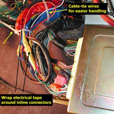
4. Install the ARM1. Place the ARM1 in the mounting location you selected and route the wires to the ECM. For a glovebox installation, look at my web page about glovebox removal and notice the small hole drilled in the back of the glovebox. Connect the ARM1 wires to the short wire sections spliced into the ECM wires (isn't this better than splicing the ARM1 wires directly into the ECM wires?). Triple check all your work then wrap electrical tape around the inline disconnect terminals. Re-connect the 22-way connector to the ECM. Then bundle wires together and secure them with cable ties.
5. Put the ECM back in. Put the ECM back in place by reversing the removal instructions above but do not put the floor panel side panels back on. Reconnect the battery negative terminal and start the car. Look and listen for any problems near the ECM and of course, if there is smoke, sparks, or fire immediately (if not sooner) shut the engine off and fix the problem. Check the ARM to see if it is working. If everything is alright, turn the engine off and install the floor console side panels.
Page last updated December 19, 2004.