Illustrated Guide to the Mitsubishi 3000GT AWD System

by Jeff Lucius

These pages are still in development. I will add more pictures as I am able to disassemble components or as others send them (pictures or components) to me. If you have comments about this web page or corrections for its contents, please send an email to jlucius@stealth316.com.

Part 1  Acknowledgments
Overview
Part 2  Transaxle Assembly
Transaxle Problems
Part 3  Center Differential/Viscous Coupling Unit
Part 4  Synchronizers
Part 5  Rear Differential, Driveshaft, and Axle Assemblies
Part 6  Propeller Shaft Assembly
Front Driveshaft and Axle Assemblies
Gear Reduction Ratios
Speed in Gears


Synchronizers

Components

The helical drive gears in our transaxles are mounted on either the input shaft or intermediate shaft. Riding on needle bearings, they spin freely on the shaft they are mounted to and remain fully meshed at all times with their corresponding gears on the other shaft. The synchronizer locks the drive gear to the shaft so that engine torque can be transmitted to the output shafts. Most synchronizer assemblies can select one of two gears, such as the assembled 1st-2nd gear synchro shown below where the 1st-speed gear is selected. There are "cones" on the gear and synchro that assist in matching the shaft and drive gear speeds before the clutch gear teeth (on the gear and synchro) fully engage.

The W5MG1 and W6MG1 transaxles use two different styles of synchronizers. The 1st-2nd speed synchro is the dual cone type and its operation is described in detail below. All of the other synchros are a single cone (also called single ring) type. The synchronizer assembly consists of a hub, which is spline coupled to the input or intermediate shaft, a sleeve, which connects to the shift fork, and a cone or ring, which assists in matching the synchro and gear rotating speeds. Three keys lock the sleeve in place with the hub by use of a ball and spring. Chamfers (or beveled edges that act like gear teeth) lock together the clutch gear that is welded to the drive gear and the synchro cone (or ring). Except for the reverse ring, rings and cones are lined on the inside, and outside for 1st and 2nd, with friction material that looks like it contains brass. The reverse ring looks like it is made of sintered metal that probably contains bronze and brass and maybe silica and graphite.

Synchro comparison

1-2 gear/synchro assembly together 1-2 gear/synchro assembly apart

Synchro detail 1

1st gear assembly

W5MG1 synchro assemblies

1st-2nd synchro assembly

Detail of key with ball and spring

3rd-4th synchro assembly

5th-reverse synchro assembly - 5th

5th-reverse synchro assembly - reverse side

Operation of the 1st-2nd Synchronizer

The components of the double-cone 1st-2nd speed synchronizer are described above. The inner cone, ring, and outer cone are always in contact. The inner cone is coupled to the outer cone by the three projections (white arrow in the picture above). The outer cone is coupled to the synchronizer hub by the three projections on the cone's outer circumference and the three notches in the hub by the keys (cyan arrow in the picture above). The ring is coupled with the clutch gear at six locations, using projections on the ring and slots in the clutch gear. The inner and outer cones become one unit with the synchronizer hub and all three rotate together. The ring becomes one unit with the speed gear and both rotate together.

synchro operation 1       
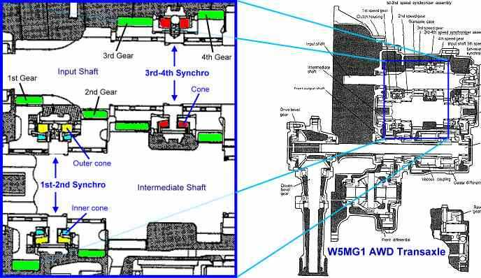
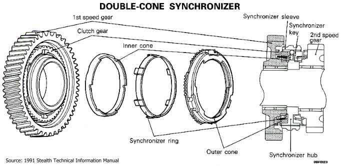
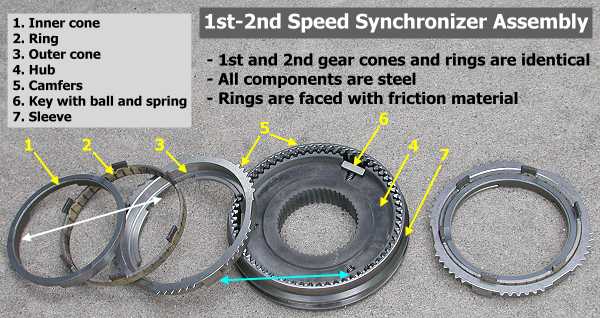
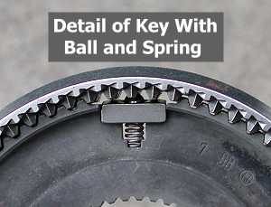
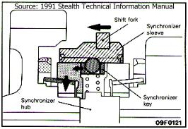
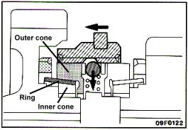
The shift fork moves the synchro sleeve to the left when the shift lever is moved toward first speed. Because the ball in the synchro key is pressed into the sleeve by the spring, the synchro sleeve and key are joined and move to the left.
synchro operation 2       As the shift fork continues to move to the left, the sleeve pushes the ball down into the key, then crosses over the key.
synchro operation 3       
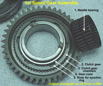
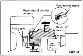
At this point, the chamfer of the outer cone spline and the chamfer of the sleeve spline come into contact. As a result of this contact, a pushing force is generated in the outer cone. As the friction torque increases between the ring and outer and inner cones, the difference in rotation speed of the 1st-speed gear and synchronizer hub reduces.
synchro operation 4       
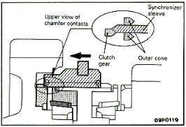
The shift fork continues to press the synchronizer sleeve to the left and the sleeve spline and outer cone spline mesh, that is, the outer cones moves "into" the sleeve.
synchro operation 5       
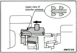
As the sleeve continues to move to the left, the sleeve spline chamfer comes into contact with the clutch gear chamfer. The clutch gear spline and synchronizer sleeve spline mesh to complete the shift to 1st speed.

Back to top of this page
Part 3   Part 3          Part 5    Part 5

Back Home Forward
Except for the small gif and jpg images, the content, images, photographs, text, and multimedia displayed are Copyright ©2000-2002 by Jeff Lucius and K2 Software. All rights reserved. No part, section, image, photo, article, or whole of this site may be reposted or redisplayed without permission of the author.
Page last updated March 17, 2002.