CAS Replacement on the DOHC 6G72,
1991-1992 Mitsubishi 3000GT/Dodge Stealth
by Jeff Lucius
Introduction
These instructions supplement the service manual's instructions on how to remove and replace the CAS on 1991 and 1992 Mitsubishi 3000GT and Dodge Stealth DOHC models. Please read all of the instructions before beginning this procedure. The CAS has part number MD153464 and has a list price of $458.33. With the club discount, I paid $343.75 for it from Tallahassee Mitsubishi (Tallahassee, FL, toll-free: 888-825-5648).
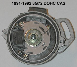
The crankshaft angle sensor and camshaft angle sensor are both in the same housing for 1991 and 1992 DOHC models. That housing is located on the rear end of the left-bank intake camshaft, just to the front of the throttle body. I refer to both sensors and their housing collectively as the CAS. Beginning in the 1993 models (June 1, 1992 production date) and continuing till the end of production, the crankshaft and camshaft position sensors were separated and moved to in front of the engine. The 1991-1992 CAS can be adjusted to set basic ignition timing. The 1993+ sensors cannot be adjusted.
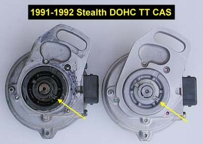
The 1991-1992 sensors uses a single disk with concentric rings of slots cut into it along with two LEDs and two photodiodes. As a slot passes between an LED and photodiode a small amount of current is generated by the photodidode as the LED light hits it. The outer ring has 6 slots and represents the crankshaft position sensor. The inner ring has 4 slots and represents the top dead center (TDC) sensor (also called the camshaft position sensor). The engine control unit uses both these signals to determine which cylinder is on either the compression or exhaust stroke (it makes no difference with our three coils and wasted spark ignition system). This information is used for ignition timing and fuel injection.
The CAS and TDCS on 1993 to 1999 models contain a Hall-effect switch that generates a voltage pulse from the decrease in magnetic flux as a vane on the screening plate passes by it. The 1993+ sensors put out the same number of pulses as the 1991-1992 sensors. For a detailed explanation of how the engine control unit utilizes these pulses to control ignition timing see my web page 2-ignitionsystem.htm. If you are interested in using a 1991-1992 CAS with a 1993+ ECU, or a 1993+ CAS and TDCS with a 1991-1992 ECU, please read my web page 2-cas_conversion.htm.
You will not need many tools to remove and replace the CAS: 10- and 12-mm sockets with wrench and extensions, a small slotted screwdriver or similar tool, pliers, some string, and a pencil or fine-tipped permanent marker. Few parts need to be removed to get access to the CAS. I wanted the engine harness and plug wires out of the way and so include these steps in the instructions below.
Removal
1. Battery. Disconnect the negative battery terminal. Be sure you have security codes if any devices need them. The CAS does not receive current when the ignition switch is off, but I think it is a good practice to disconnect the battery anytime I am working in the engine compartment.
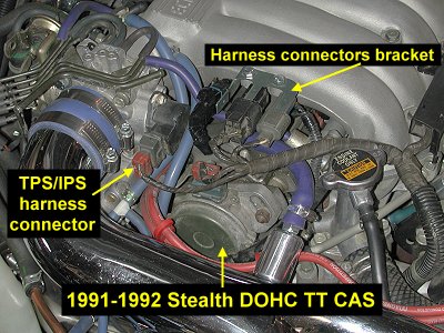
2. Harness connectors bracket on plenum. Remove the two 10-mm screws that attach the bracket to the plenum.
3. CAS and TPS/IPS harness connectors. Using a small slotted screwdriver, carefully pry on the spring clamp to remove it from the CAS harness connector. Also do this with the throttle position sensor/idle position switch connector. Do not drop these little wire locking clamps. Remove the harness connectors from the CAS and TPS/IPS. I used some string to tie this part of the harness away from the CAS. Be careful with an old harness; the insulation can be brittle.
4. Hoses. Remove or tie out of the way any PVC or vacuum hoses near the CAS.
5. Spark plug wires. Remove the spark plug wires bracket from the CAS adapter housing. Remove the rear bank of plug wires from their coils and get these away from the CAS.
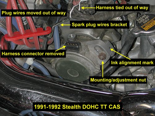
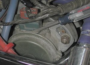
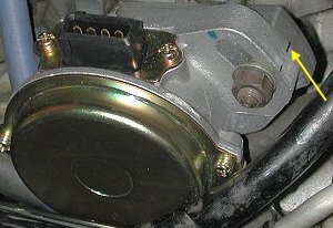
6. Alignment mark. Using a pencil or fine-point marker, put a small mark on both the CAS and its adapter as shown in the photograph above. You will use this during installation to minimize changing the ignition timing.
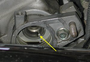
7. CAS. Remove the 12-mm nut and lock washer that attaches the CAS to its adapter bracket. Nothing else secures the CAS. Firmly pull on the CAS away from the adapter bracket. Be very careful to not disturb the rotating part of the CAS as you remove it. Do not worry too much because it does not turn that freely, but you need to know the position of the shaft's mating mark to install the new CAS in the same position as the old one was in to avoid having to reset the ignition timing.
Prepare the new CAS
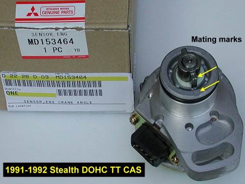
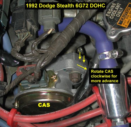
1. Match mating mark positions. Rotate the shaft of the new CAS so that the shaft's mating mark is in the same position as on the CAS you just removed. See the photograph below as an example. The position of the mating mark could be different for your CAS depending on where piston #1 came to rest when the engine stopped.
Installation
2. Transfer alignment mark. Carefully place a mark on the new CAS that is in the same position as the alignment mark you made earlier on the old CAS before you removed it.
2. CAS. Apply a light coating of engine oil to the o-ring on the new CAS. You can just use some of the oil that has seeped into the adapter. Wipe the rest of the oil out of the adapter and carefully insert the new CAS. You may have a little bit of trouble getting the arms on the CAS shaft to slide into the slot in the adapter housing. Once you get everything lined up, push firmly to fully insert the new CAS. Put the lock washer and nut on the stud. Rotate the CAS so that the alignment marks you made line up. Tighten the nut.
3. Wires and hoses. If you removed them, put the plug wires and bracket and hoses back where they belong.
4. Harness connectors and bracket. Put the harness connectors back on the CAS and TPS/IPS. Pliers can help hold the wire clamp for the TPS/IPS connector as you install it. Put the connectors bracket back on the plenum.
5. Battery. Inspect the area you have been working in to be sure all electrical parts and hoses are where they should be. Re-attach the battery negative cable and be sure the engine starts and that there is no electrical problem related to the work you just performed.
6. Timing. If you were careful in replacing the CAS, ignition timing may not have changed. However, you should check the basic timing. Follow the instructions for this in the service manual or take a look at my web page 2-ignition-timing.htm. When I checked my timing after replacing the CAS, basic timing was about 3º retarded (ATDC). I adjusted basic timing to 7.5º advanced (BTDC). Because I did not check basic timing right before replacing the CAS, I do not know if it was retarded before replacing the CAS or if there is a normal variation between CAS units. The picture below shows how much I had to adjust the CAS to get the correct basic timing advance.
Page last updated October 14, 2005.