Reading Diagnostic Codes on the
1991-1993 Mitsubishi 3000GT/Dodge Stealth
by Jeff Lucius
Introduction
These instructions supplement the service manual's instructions on how to read the diagnostic codes on 1991 through 1993 Mitsubishi 3000GT and Dodge Stealth cars. Please read all of the instructions before beginning this procedure and refer to the service manual for additional information. Please note that, at least in my 1992 Dodge Stealth service manual (p. 14-98), the service manual may incorrectly identify the ground terminal in the diagnostic connector. The service manual for the 1992-1996 3000GT (p. 13A-50) does identify the correct ground terminal. For the correct identification of all terminals in the 1991-1993 diagnostic connector, see my web page 2-diagconn.htm.
For 1994 and 1995 models, the diagnostic port was re-located to under dash knee protector near the driver's right leg. According to the service manual, the codes can be read by grounding terminal 1, turning the ignition on (do not start the engine), and observing the pattern of flashes of the check engine (CE) light on the dash. For 1996 and newer models, the diagnostic port is in the same location. However, the codes can be read only using a MUTII or other OBDII scanning tool. Use the Diagnosis Chart from the appropriate-year service manual to interpret the patterns.
The engine control unit (ECU) monitors many of the input and output signals that it receives. It performs checks on these signals, either continuously or under specific conditions, to identify irregularities. These irregularities are explained in detail in the service manuals in the "MPI System" section. The ECU stores a code for each irregularity found until either battery power is removed from the ECU (by pulling a fuse or removing a battery cable) or the code is erased using a scanning tool. Turning the ignition off does not erase a code.
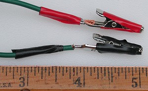
The only tools you need to read the codes on the 1991 through 1993 models are an analog voltmeter and two wire jumpers with 1" clips on at least one end of each.
Procedure
1. Connect voltmeter. Remove the cover, if present, from the diagnostic connector. With the ignition in the OFF position, connect the leads of the analog voltmeter as shown below, positive lead to terminal 1 and negative lead to terminal 12. I add some tape to the clips to be sure they do not short against an adjacent terminal. Turn the voltmeter on and set the range to 10 DC V.
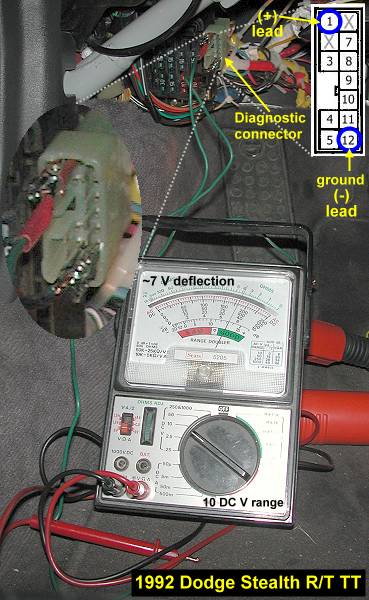
2. Read the codes. Place the ignition switch in the ON position (2 clicks) but do not start the engine. Observe the pattern of needle deflections. The pattern is a sequence of long and/or short sweeps. If there are no errors, then the "normal code" is a continuous repetition of short sweeps. See an example in misc/metersweeps.mov . If there are multiple codes, they will be indicated sequentially from the smallest code number. If there is not a code displayed, the ECU itself may be faulty.
3. Interpret codes. Use the diganosis charts from the service manual, reprinted below, to determine the diagnosis item and possible remedy. The service manual may provide additional diagnostic and repair procedures.
Page last updated June 10, 2003.