Fuel Injection Control and Fuel Cut
in the Mitsubishi 3000GT VR4 and
Dodge Stealth R/T Twin Turbo

by Jeff Lucius

   Topics
         
Introduction
Fuel Injection Driver Circuits
Fuel Injector Activation Timing
Fuel Injection Amount Control
Fuel Cut
Summary
References

Introduction

This technical note describes fuel injection timing and control in the Mitsubishi 3000GT VR4 and the Dodge Stealth R/T Twin Turbo. The 6G72, DOHC, 24-valve, turbocharged, 2.972-liter, V6 engine uses a multipoint fuel injection system that is electronically controlled. Fuel injection control for the non-turbo DOHC and the SOHC 6G72 engine is basically the same except for the specific features related to turbocharging. The fuel injectors themselves are described more completely in my web page 2-injectortypes.htm.

The cylinders are arranged and numbered as shown below. Because each piston begins its combustion stroke 120º before the next numerically successive cylinder, there are three "pairs" of cylinders, 1-4, 2-5, and 3-6. Each cylinder pair move up and down together and are at top dead center (TDC) at the same time.
Mitsubishi 6G72 cylinder numbers
The in-tank electric fuel pump and the fuel pressure regulator provide pressurized fuel to the six fuel injectors mounted in the cylinder head intake ports. Each injector is activated independently by the engine control module (ECM). Because the injector nozzle spray area is constant and the fuel pressure is constant, the amount of fuel injected is determined by how long the injector solenoid coil is energized, that is, by how long the ECM grounds the injector electrical circuit. The basic injection activation duration is determined by the intake air volume of each cylinder per engine revolution (A/N), which is determined using the air flow signal from the mass air sensor (MAS) divided by the engine speed (the RPM determined from the crank angle sensor, CAS), with corrections applied for a selection of the following input signals depending on the driving situation and operating conditions.

Fuel Injection Driver Circuits

In general, there are two types of fuel injection driver circuits: voltage controlled and current controlled. In current-controlled circuitry, the current through the low-resistance injectors is limited by controlling the gain of the driver transistor inside the ECM. In voltage-controlled circuitry, which is used by Mitsubishi in all 3000GT/Stealth models, the resistance of the overall circuit limits the voltage in the circuit and therefore limits the current through the injector coil windings. In the turbo models, an external resistor is added to the circuit to reduce current in the low-resistance injectors. The non-turbo models do not have the external resistor and use instead high-resistance injectors. As shown in the figure below, in the voltage-controlled circuit the low-resistance injector with an external resistor opens quicker than the high-resistance injector because 1) the solenoid coil is designed with fewer turns and larger-diameter wire allowing the solenoid to respond faster and 2) the current is higher to the coil forcing the solenoid to open the injector faster.

Fuel injection driver circuitry

Fuel Injector Activation Timing

The fuel injectors are activated either sequentially or simultaneously depending on the driving situation. In sequential operation, each injector fires in succession, based on crankshaft position for each cylinder, once during 720º of crankshaft rotation (once every two revolutions). Fuel injection is timed to deliver as much fuel as posible before the intake valve opens to provide optimum throttle response, best fuel economy, and lowest overall emissions. During simultaneous injection, all injectors fire at the same time based either on crankshaft position or on time interval.

Sequential Injection - normal operation
It is not clear from the available references (listed below) exactly when the fuel injection activation signal begins. The pattern Mitsubishi uses in other engines is to use the either the beginning or the end of the crank angle sensor (CAS) signal of one cylinder to activate the injector of another cylinder. The CAS signal is 50º "long" and starts at 5º before top dead center (BTDC) and ends at 45º after top dead center (ATDC) at the start of the combustion stroke. For the 6G72 this means that the start of the CAS signal for cylinder No. 1 probably activates the injector for cylinder No. 5 during the exhaust stroke (see the figure below); and cylinder No. 2 activates cylinder No. 6, and so on. On the other hand, it is possible that the end of the CAS signal for cylinder No. 1 activates the injector for cylinder No. 5 later in the exhaust stroke or even for cylinder No. 6 very late in the combustion stroke. It is unlikely that the cylinder No. 1 CAS would activate cylinders Nos. 1, 2, 3, or 4 because activation would start too late during the intake or compression stroke. If the three possible options are considered, then injector activation starts sometime between 18º before bottom dead center (BBDC) in the combustion stroke to 78º BTDC in the exhaust stroke.

Mitsubishi 6G72 sequential injection 1

Simultaneous Injection - start cranking
Immediately as the engine starts cranking, the injectors operate in "batch" mode. All injectors activate simultaneously in synchronization with the CAS signal for each cylinder until the CAS for cylinder No. 1 is detected. The activation duration is not described in the manuals. As soon as the No. 1 cylinder CAS signal is detected, simultaneous injection stops and sequential injection begins if the engine is warm (determined from the engine coolant temperature sensor). If the engine is cold then simultaneous rather than sequential injection continues as explained in the next section.

Mitsubishi 6G72 simultaneous injection - start cranking

Simultaneous Injection - cold start
If the engine is cold while the starter is cranking the engine, all injectors fire simultaneously in synchronization with the CAS signal from each cylinder. Injection in each cylinder occurs three times for every revolution of the crankshaft. The activation duration is not described in the manuals.

Mitsubishi 6G72 simultaneous injection - cold start

Simultaneous Injection - acceleration enrichment
During acceleration, an additional amount of fuel is injected according to the degree of acceleration. In addition to the sequential firing of the injectors, the injectors activate simultaneously every 10 milliseconds (ms).

Mitsubishi 6G72 simultaneous injection - acceleration enrichment

Fuel Injection Amount Control

The fuel injection amount is controlled to achieve a specific air-fuel ratio (A/F) in the cylinders. During normal engine operation, the target A/F is near 14.7 (a stoichiometric mixture that ideally completely combusts all the carbon, hydrogen, and sulfur in the fuel) when the ECM is operating in closed loop (or feedback) mode. When the ECM operates in open loop mode and engine power is more important than fuel economy or emissions, the target A/F is less than 14.7, called "rich", usually in the 11.5 to 13.2 range.

O2 sensor response    A/F, performance, emissions

Control During Normal Operation
The basic injector driving time, also called the activation duration or the injector pulse width (IPW), is determined in many steps. First, engine load is calculated using just the air flow sensor and engine speed (crank angle sensor) for closed-loop operation, and the air flow sensor, engine speed and intake air temperature and barometric pressure for open-loop operation. The volume air flow divided by the engine speed determines the engine load factor, called A/N (and displayed on the factory "boost gauge"). As volume air flow increases, injection duration increases. As engine speed increases, injector frequency increases. Next, the ECU selects closed- or open-loop mode based on throttle opening, engine speed, vehicle speed, and fuel trim and air flow maps. Then corrections to the target fuel volume are adjusted based on the following and an injector pulse width calculated: engine speed, engine coolant temperature, throttle position, intake air temperature, barometric pressure, detonation sensor, fuel injector scaling, and battery voltage (deadtime compensation). The flow chart below summarizes the interaction of components.

Mitsubishi 6G72 fuel injection control during normal operation

Mitsubishi 6G72 coolant temp correction Fuel vaporization is poor when the engine is cold. The injection duration is increased (A/F richened) when the coolant temperature is below 80ºC (176ºF) to improve driveability.
Mitsubishi 6G72 IAT correction At any particular volume air flow, a change in air temperature changes the air density. The colder the air is, the denser the air becomes. When the air temperature is below 25ºC (77ºF), the basic injection duration is increased, and when the air temperature is above the standard temperature the duration is decreased.
Mitsubishi 6G72 barometric pressure correction Air density at a particular volume flow decreases as barometric pressure decreases. The injector duration is adjusted when the atmospheric pressure is above or below the standard value of 760 mm Hg (29.9 in Hg).
Mitsubishi 6G72 acceleration correction Because fuel is denser than air and cannot move into the cylinder as quickly during engine acceleration, a momentary lean condition can exist. To compensate for this, the injection duration is increased. Extra injection pulses also may be delivered (see above). Injection duration is reduced during deceleration to improve fuel economy and emissions.
Mitsubishi 6G72 IAT injector dead time 
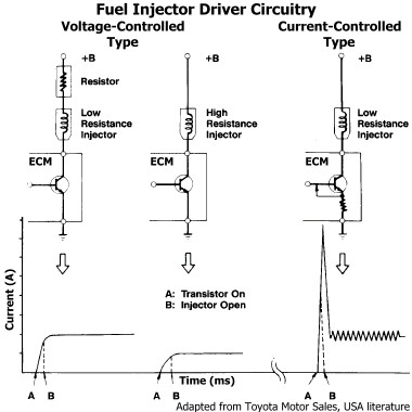
When current flows through the injector solenoid coil, the needle valve is pulled up into the injector to allow fuel to flow. The time lag between the time the current starts and the time the valve is fully open is called the dead time. Because the valve moves faster when more current is available, the injection activation signal time is decreased when battery voltage is high and increased when battery voltage is low. However, the actual opening time of the injector remains the same.
Mitsubishi 6G72 voltage compensation


Not shown in the chart above is the fact that the ECU will add up to 30% more fuel if it sees that ignition timing advance has been been decreased too much. This is part of the programmed knock control. Thanks go to Todd Day on the DSM-ECU email group for this information (10/30/2006).

Closed Loop Control (Feedback Control)
In closed-loop mode, the ECU is using oxygen sensor voltage (see figure above) in a feedback loop to restrict the air-fuel ratio to a narrow range where the catalytic converter is most efficient. That range is A/F equal to 14.7 plus or minus 1% air (0.99-1.01% lambda, where a theoretical lambda of 1.0 equals an A/F of 14.7), or ~14.55 to ~14.85 A/F. The oxygen sensor indicates a (theoretical) stoichiometric air-fuel mixture (A/F equal to ~14.7) with a voltage typically in the range of 0.45 to 0.5 volts. When the sensor output is greater than this range, there is much less oxygen in the exhaust gas than in the atmosphere and the mixture is rich (A/F is less than ~14.7). When there is excess oxygen concentration in the exhaust gas, that is, as the oxygen content approaches that of the atmosphere, the sensor sends a signal less than 0.45 to 0.50 volts to indicate a lean mixture (A/F is greater than ~14.7). If fuel injection is stopped in the engine, oxygen content in the exhaust stream will equal that in the atmosphere and the O2 sensor voltage output will be zero. Typically the ECU uses a reference voltage of about 0.4 V, which is just on the lean side of ~14.7, or a lambda ~= 0.995. The ECU reacts to these rich and lean signals by reducing and increasing, respectively, the injector activation duration. By using this feedback control to maintain the oxygen content in the exhaust stream within a very narrow range, the three-way catalytic converter operates at its peak efficiency to reduce carbon monoxide (CO), hydrocarbon (HC), and nitrous oxides (NOx) emissions.

Closed loop mode is used generally during warm idle, low-load cruising, and low-load acceleration to reduce engine emissions. Best fuel economy actually occurs with a slightly lean mixture, with A/F a little more than 16. Despite the need to reduce emissions, there are certain operating conditions where closed loop mode is not used in order to prevent overheating the catalytic converter or driveability problems. These situations include:
Open Loop Control (Preset Map Control)
In open-loop mode, generally during moderate-load and high-load acceleration, the ECU is not using the oxygen sensor information and instead relies on preset maps stored in ROM (read-only memory). These maps use engine speed and A/N to modify the basic injector activation time toward a target A/F. A/N is equivalent to engine load and is the amount of intake air into each cylinder per engine revolution. As mentioned above, correction factors are applied to the map-adjusted drive times. Using information from the wizards who de-code the DSM ECUs, our 3S ECU, which has similar programming, will select open-loop mode regardless of engine load when the following occur. I do not know exactly what these values are for all models under all engine operating conditions. If you have been datalogging during a wide variety of driving conditions you may be able to determine the approximate throttle opening and car speed that forces open-loop mode for your car.

Below is an example "fuel map", courtesy of Matt Jannusch and the DSM-ECU Yahoo! Group, for a 1995 3000GT Spyder VR4. The actual values in the ECU are in the range of 0 to 255, with 128 representing a 14.7 A/F. A map value of 150 represents an A/F of (128/150)*14.7 = 12.544. Notice that the map is not a smooth progression of numbers. The "fuel map" for an engine is produced by systematically varying engine speed and load and then finding the optimal A/F ratio to produce the desired combination of power, fuel economy, low emissions, and knock prevention. The ECU interpolates between values when engine speed and load fall between map sites. Note how rich the ECU is trying to make high-rpm and high-load operation with A/F ratios of 10.2 to 10.3. Better values would be closer to 11.5 if engine knock (detonation) can be controlled. Also notice the values near 14.7. These orange cells indicate the combinations of engine load and RPM where the ECU expects there should be or could be closed-loop operation, but because of perhaps an oxygen sensor malfunction the ECU is in open-loop mode.

Example fuel map

Fuel Cut

When certain conditions occur, both open-loop and closed-loop controls are ignored and fuel delivery is reduced or completely shut off, that is, the ECU reduces activation times or does not send the injector activation signals. This is called fuel cut. There are three situations in which this occurs.
Overrun protection.
Fuel is cut when engine speed exceeds 7300 RPM to prevent internal damage to the engine. The fuel activation time is reduced to zero in less than a second for the rear cylinder bank. If engine speed remains above 7300 rpm, fuel injector activation time is also reduced toward zero for the front cylinder bank. Fuel injector activation times are increased when engine speed falls below the threshold value. My web page 2-rpmfuelcut.htm discusses this type of fuel cut in greater detail and presents a datalog. Adding a daughter board to the ECM can raise this threshold value. Our valvetrain is reported to be capable of 8000 to 8300 RPM without significant valve float or damage.

Overboost protection.
There is no sensor in the 3S cars to measure boost pressure. In 1996 and newer models there is a manifold absolute pressure (MAP) sensor, but it is used only for emissions purposes. The boost meter in the dash is a current-type meter that is controlled by the ECM. The ECM receives the air flow signal and engine speed signals and calculates the engine load. The boost meter is displaying the calculated A/N value rather than actual manifold absolute pressure. When the A/N exceeds a certain value at a particular RPM the ECM believes that excessive supercharging pressure exists and it stops sending the injector activation signals. Fuel flow resumes when the A/N falls below the threshold value. Note that overboost protection can occur at any RPM if the airflow is high enough (the threshold A/N changes over the RPM range). This overboost protection can be avoided by either reprogramming the ECM with a daughter board or by the use of an airflow signal conditioner (ASC) and larger fuel injectors. When larger fuel injectors are installed, the ASC reduces the airflow signal and the threshold value is rarely if ever exceeded.

Deceleration fuel cut.
Both emissions and fuel economy are adversely affected if fuel is delivered during closed-throttle deceleration at higher engine speeds. Therefore, the ECM does not send the injector activation signals to either cylinder bank during this situation. Once the engine slows, fuel delivery is resumed. The fuel cutoff speed and fuel resume speed depend on the coolant temperature, with both decreasing as coolant temperature increases.

Summary

The electronically-controlled, multipoint, fuel-injection timing in the Mitusbishi DOHC 6G72 operates in two modes, sequential or simultaneous, depending on the driving situation and the operational conditions. Fuel injection control also operates in two modes, closed loop, which uses oxygen sensor information in a feedback loop to maintain a 14.7 A/F, and open loop. In open-loop mode the fuel injector activation duration is determined basically using the volume air flow and the engine speed. Correction factors are then applied for the various engine-operating conditions. The figure below shows the probable range of injector activation and some examples of injector duty cycles (injector pulse width divided by the time between intake strokes) in relation to the four strokes in the Otto cycle and the valve and ignition timing events.
Mitsubishi 6G72 Timing Events

References

Chrysler Corporation, 1988, 1990 Laser Technical Information Manual: Part number 81-699-9002, various pagination.
Chrysler Corporation, 1990, 1991 Stealth Technical Information Manual: Part number 81-699-0114, various pagination. Available on-line at 2-stim.htm.
Mitsubishi Motors Corporation, 1999, 1992 - 1996 3000GT Service Manual, Vol. 1, Body and Chassis: Pub No. MSSP-001B-96 (1/2), various pagination.
Mitsubishi Motors Corporation, 1998, 1999 3000GT Service Manual, Vol. 1 & 2: Pub No. MSSP-001B-99 (1/2), various pagination.

Back Home Forward

Except for the small gif and jpg images, the content, images, photographs, text, and multimedia displayed are Copyright ©2000-2006 by Jeff Lucius and K2 Software. All rights reserved. No part, section, image, photo, article, or whole of this site may be reposted or redisplayed without permission of the authors.
Page last updated October 02, 2012.