Fuel Pump Voltage Measurement
for the Mitsubishi 3000GT/Dodge Stealth
by Jeff Lucius
Introduction
It is critically important for turbocharged models that the fuel pump receive the maximum amount of voltage available from the charging and wiring system. The alternator will try to maintain about 13.5 volts into the system. Resistive losses along the current path to the pump will reduce the voltage at the pump to something less than 13.5. If there are less than 12 volts at the pump, the amount of fuel flowing may be much less than expected and perhaps enough less to create lean air-fuel mixtures under heavy boost.
The instructions below show you how to measure the voltage at the fuel pump. Please read through the instructions and look at the pictures before attempting this procedure. After connecting up the wires as shown below to a digital volt-ohm-meter (VOM) I ran the car and saw the following numbers. At idle the pump was receiving about 6.7 to 7.0 volts. This is somewhat normal because Mitsubishi installs a resistor and a relay to reduce voltage to the pump when plenum pressure is not positive (that is, less than atmospheric). When boost is achieved (plenum pressure above atmospheric), the full system voltage is supposed to reach the pump. I saw from 10.6 to 10.8 volts as boost began to build and then watched that number drop to 10.2 to 10.3 volts as boost hit 15 psi or so and RPM approached redline. Not good!
I performed the resistor relay bypass (2-fuelpumprelaybypass.htm) and did not see any change except the voltage was higher at idle, about 10.7 volts. I moved the battery to the rear compartment and ran an 8-ga ground cable from the ground stud on the assembly frame directly to the battery about 2 feet away. There was no change in the voltage. This figures because the assembly is grounded through the gas tank, not that stud. I then rewired the fuel pump directly to the battery through a relay (2-fuelpump-rewire.htm). Now I have battery voltage minus about 0.11 volts at the pump at all times.
The tools and supplies needed include a #2 Phillips screwdriver, wire cutters, utility knife, 7-mm socket and socket wrench or 7-mm box-end wrench, electrical tape (two colors, red and black, are nice), about 18 feet of 16 or 18 gauge insulated wire, a ring connector, and a digital volt-ohm meter. Be sure the ignition is off before performing this work.
Fuel pump electrical circuit
Looking at the circuit diagrams in the service manual, I found the following current path to the pump for turbocharged models.
1) Battery [+ terminal]
2) Fusible link [30A - terminal 4]
3) Ignition switch [IG1]
4) Multipurpose fuse [15A - terminal 12]
5) Engine control relay
6) Fuel pump relay
6a) Resistor [switched by ECU at idle through the pump relay]
7) Fuel pump
8) Chassis ground [-] through fuel pump assembly frame to gas tank to body/frame
Preparation
1. Storage bin. Remove the spare tire and right-side storage bin. I find it easier to work in the rear compartment if the carpet, the cardboard cover, and the left-side bin are removed also. There are two push-in plugs that hold the carpet in and four Phillips screws that attach the cardboard cover. Phillips screws attach the storage bins.
2. Access cover. Remove the four Phillips screws and then remove the fuel pump access cover.
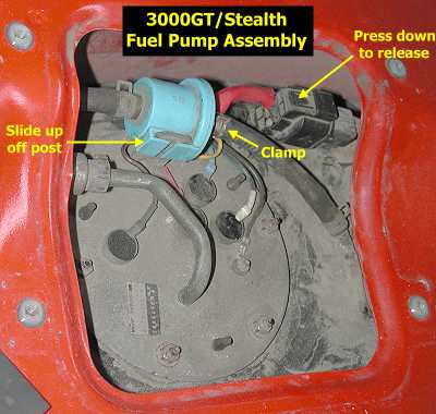
3. Blue valve and hose. Pinch the spring clamp on the vent hose that leaves the blue valve toward the back of the car and slide the clamp off the valve. Lightly grasp the hose and twist it a little to break its seal on the valve nipple. Slide the hose off the nipple and bend the hose out of the way. Slide the blue valve up off the post.
4. Connector. Separate the electrical connector by pressing down on the tab and pulling that piece toward the front of the car.
Attaching the wires
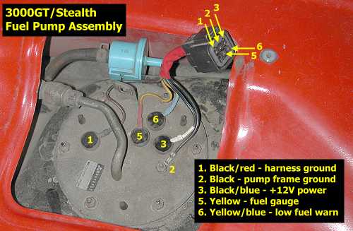
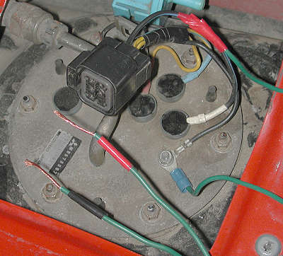
1. Identify wires. Carefully cut off the red plastic wrap. Separate out the black wire with the blue stripe (this is power wire to the pump) and then wrap electrical tape around the other wires. I did some continuity tests to see how the two ground wires were used. The black wire with a red stripe (#1 in the picture below) is the harness ground wire and connects to the yellow wire (the fuel gauge) with about 14.7 ohms resistance and to the yellow wire with a blue stripe (the fuel level warning switch) with about 3.142 k-ohms resistance. There was no contunity between this ground wire and the power wire (that is, the fuel pump) or the other ground wire. The solid black wire is the ground wire for the fuel pump assembly frame. The fuel pump is grounded to the assembly frame (down inside the tank). There was about 1.0 to 1.1 ohms resistance measuring between the black wire (assembly frame ground) and the black wire with the blue stripe (pump power).
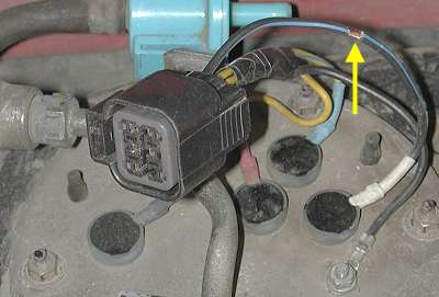
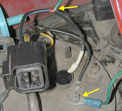
2. Tap the power and ground wires. Cut two pieces of 16 or 18 gauge insulated wire about 8 to 9 feet long. these will be the two jumper wires. On three of the ends strip the insulation back about 3/4 inch. On the fourth end attach a ring connector. On the power wire for the pump (black with blue stripe), carefully strip away about 1/8 inch of insulation from the middle of the wire. Use wire strippers to break the insulation (cut only through the insulation, not the wire underneath) in two places and then use a utility knife to remove the 1/8 inch piece of insulation between the cuts. Wrap one end of the jumper tightly around the exposed power wire and then wrap that connection with electrical tape. On the other end of the "power" jumper wire, wrap red electrical tape around it to provide for positive identification. Remove the 7-mm nut that attaches the black ground wire and add the ring connector for the "ground" jumper. Put the 7-mm nut back on. Wrap some black tape around the other end of the "ground" jumper wire. Check for continuity by connecting the VOM to the two loose ends of the jumper wires. I measured about 1.1 ohms, the same as between the power and ground wires before the jumpers were attached.
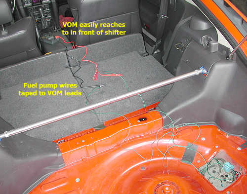
3. Attach the VOM. Attach the wires to the VOM leads. For the smooth leads I had, I just wrapped the jumper wires around the leads, power wire to the POS lead and ground wire to the NEG or common lead, and then wrapped the connection with electrical tape. Be very careful to never let the exposed positive (power) wire from the pump touch any metal or grounded part of the car. Check the resistance on the setup; mine was 1.2 ohms, and then set the VOM to measure DC volts.
4. Re-attach hose and connector. Re-connect the electrical connector. Slide the blue valve back onto its post. Re-attach the hose to the valve. You are now ready to measure the voltage at the pump. When you are all finished, remove the wires from the pump assembly and wrap the power wire with electrical tape to protect the exposed section. Put the rear compartment items back in.
Page last updated June 17, 2002.