Ignition Coils Removal, Inspection, and Installation
on the DOHC 6G72 engine
in the Mitsubishi 3000GT and Dodge Stealth

by Jeff Lucius

Introduction

Automotive ignition coils are step-up transformers that consist of two separate wires wound about a soft-iron core. One wire, called the primary wire, is thicker and has less turns (a turn is one wrap of the wire about the core) than the other wire, called the secondary wire. The primary windings surround the secondary windings. Our engines use an electronic inductive-discharge ignition system (2-ignitionsystem.htm). Energy is stored relatively slowly in the primary windings and then released rapidly into the secondary windings.

While the transistors in our engine control unit (ECU) and power transistor unit ground the coil's primary wire circuit (also called the Low Tension circuit), current and voltage increase through the primary windings and a magnetic field (flux) is produced around the coil and strengthens until the field maximizes. The time (traditionally measured in camshaft degrees) that the ECU holds the coil's circuit grounded is called dwell (analogous to the points being closed in an older distributor system). In our coils, the (dwell) time required to maximize the magnetic field should be around 0.004 seconds (that is, 4 milliseconds or 4 ms). Some modern, high-performance coils need only 2 to 3 ms. Other coils need as much as 8 to 9 ms to maximize the magnetic field. The current in the coil primary windings is limited by the ECU to 6 amps. The dwell time is also limited by the ECU to no more than 75% of the available time, which is one engine revolution because of our wasted spark ignition system. At 7500 rpm there are 8 ms between coil firings (60,000 divided by 7,500). At this engine speed, dwell time is limited to less than 75% of 8 ms or less than 6 ms. In other words, there is plenty of time even at 7500 rpm, which is above the factory redline, for the coils to completely charge.

When it is time to fire the spark plugs, the ECU releases the ground to very quickly stop current in the primary wire. The magnetic field collapses first through the primary windings producing a current in these windings (a process called self induction). This current, typically with a potential in the range of 200 to 400 volts, produces its own magnetic field, which in turn produces an electromagnetic force (emf) in the secondary windings (also called the High Tension circuit) by a process called mutual induction. When there is a complete circuit on the high tension side, that is when both spark plugs fire, then there is also an induced current generated in the secondary windings with a voltage directly proportional to the self-induced voltage in the primary windings times the ratio of the number of turns in the secondary windings to the number of turns in the primary windings, and directly proportional to the resisitance in the circuit. A small bit of power is lost to inefficiency in the coil. Typically there are 65 to 135 secondary turns for every primary turn. The final result of the initial magnetic field collapse is a very-high voltage current (with proportionally lower amperage) through the secondary windings and the spark plug wires. The voltage produced in the secondary ignition system is the minimum amount required to produce sparks across the two spark plug gaps. The wasted spark should require from 3,000 to 6,000 volts. The combustion spark may require from 12,000 to over 40,000 volts. Once a spark is produced, resistance in the circuit drops drastically and the energy is quickly dissipated.

DOHC 6G72 Ignition Coils 
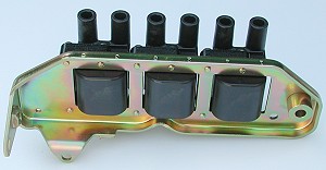
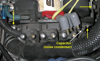
Three ignition coils are used in the distributorless ignition system on the Mitsubishi 3000GT and Dodge Stealth DOHC engine (turbo and non-turbo). Each ignition coil fires a pair of spark plugs simultaneously: one with the piston before TDC on the compression stroke and the other one with the piston before TDC on the exhaust stroke. The spark during the exhaust stroke is wasted and the basically inert exhaust gas does not combust. This is called a wasted spark ignition system (see my web pages 2-sparkplugtech.htm for more information on spark plugs and 2-timing.htm for information on timing events).
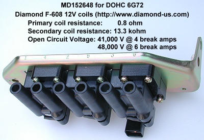
The Diamond Electric F-608 12V 2-terminal coil is used for all years of the 3000GT/Stealth that have the DOHC engine. This identification is on the bracket for early production and is stamped into the coil for later production. Diamond's web site publishes a small bit of information about this coil on the web page http://www.diamond-us.com/Pages/Products/Coil2pStd.html. Some specifications for this coil are listed below. I talked to Diamond's office in Michigan and asked for additional specifications. I was told that additional information (such as inductance and turns ratio) was proprietary and so not available.


The same ignition coils assembly is used on all years and models of the DOHC 6G72 V6 (turbo and non-turbo). It is part number MD152648 and includes all three coils mounted on a bracket (as shown below). I paid $100.89 plus shipping for MD152648 at Tallahassee Mitsubishi (1-888-825-5648).

Ignition coils top    Ignition coils bottom 2

Ignition coils back    Ignition coils bottom 1

These instructions supplement the service manual's instructions for removing, inspecting, and installing the ignition coils. Please read all of these instructions before beginning this operation. The suggested tools include: a Phillips and slotted screwdrivers, an 10-mm and 12-mm sockets with 6" extension and wrench, 12-mm open/box end wrench, visegrip-type pliers, regular pliers, and masking tape.

Removal

1. Battery ground cable. With the ignition off, remove the negative battery cable from the battery. Be sure you have security codes for any devices that might need them before you do this.

3. Intake hoses/pipes. I removed my ARC2 MAS and air filter, my aftermarket Y-pipe, the "T" hose that the MAS connects to, and my aftermarket metal intake pipe that goes to the front turbo. I place clean rags into all openings (IC pipe, intake hose, turbo, throttle body). This gives pretty good access to the coils and power transitor unit, which is right below the coils. Better access can be had if the upper coolant hose is removed. If you want to remove this hose you can do it the easy, messy way (disconnect the hose at the radiator and catch maybe a quart or two of sticky fluid in rags and containers) or the harder, correct way (remove undercovers and maybe some active aero stuff and loosen the petcock at the lower driver's side corner of the radiator to drain fluid out of the drain hose into a container).

4. Capacitor. Remove the screw that attaches the capacitor to the lower front corner of the bracket. I used visegrip pliers to loosen the screw. The capacitor is attached to the wiring harness. Mitsubishi calls this component the Noise Condenser (illustration 54-550 in CAPS). The part number, MB543146, is the same for all years. The picture below shows the screw that attaches the capacitor (yellow arrow near capacitor) and the two mounting screws (yellow arrows at either end of the bracket).

Ignition Coils

5. Harness and ignition wires. Disconnect the wiring harness connector from the bracket by pressing in the lever (underneath) and pulling on the connector. Remove the ignition wires from the coil terminals. Note that the cylinder numbers for each terminal are stamped into the top of the bracket. Toward the back of the bracket a piece of the wiring harness is attached to the bracket using a plastic snap-in piece. I simply cut the plastic piece to disconnect it from the bracket. I did not replace it nor do I know the part number for it. I imagine the dealerships have bins of these things laying around.

6. Front turbo coolant pipe bracket. Remove the 10-mm screw on the bottom of the coils bracket. This attaches a bracket that holds the small coolant pipe for the front turbo center housing rotating assembly.

7. Coils with bracket. Remove the two 12-mm mounting screws that attach the coils and their bracket to the front cylinder head. The shorter one goes in front. Extract the coils and bracket together through the top. This would be much easier if the top radiator coolant hose is removed.

Inspection

The service manuals, in section 16 for the 3000GT manuals or in section 8 for the Stealth manuals, offer a few troubleshooting hints plus some service and inspection tests. Under troubleshooting the manuals suggest that malfunctioning coils can lead to one or more of the following symptoms: (1) insufficient or no spark, (2) rough idle or stalls, and (3) poor acceleration. I would add that if a coil is bad, the pair of plugs connected to the coil will both lack spark. Once the coil assembly is off the engine, individual coils can be switched to see if a problem follows a coil. If you have a digital storage oscilloscope (DSO) the newer manuals present example waveforms you can compare to observed waveforms. With an analog or digital volt-ohm meter (VOM) you can perform the two tests shown below.

Ignition Coils primary resistance test 
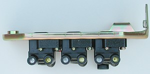
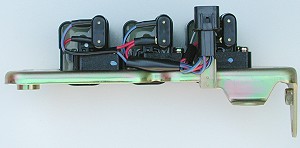
1. Primary coil resistance. Before you start, switch the digital VOM to measure resistance and touch the two leads together. Note the value indicated (mine said 0.6 ohms) and subtract this value from the next three measurements. If using an analog VOM meter, use the zeroing dial for the resistnace setting to eliminate the offset. Connect the VOM positive lead to terminal [3] in the harness connector on the coils bracket. Measure the resistance between between terminal [3] and the remaining terminals by connecting the VOM negative (ground) lead sequentially to terminals [1], [2], and [4]. Note that terminals [1] and [2] are near the release lever catch and terminals [3] and [4] are near the smooth side of the connector. The service manuals indicate a standard value of 0.67 to 0.81 ohms. All of my old (65,000 miles and 11 years) and new ignition coils measured 0.8 ohms (1.4 minus 0.6 ohms).

Ignition Coils secondary resistance test 
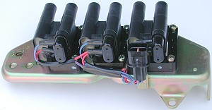
2. Secondary coil resistance. Leaving the VOM set to measure resistance, connect the positive and negative leads to the metal parts inside the two high-voltage terminals on a coil. Repeat for all three coils. The standard value is 11,300 to 15,300 ohms. My old coils measured 13,910, 13,820, and 13,410 ohms for coils A, B, and C, respectively. The new coils measured 13,310, 13,340, and 13,200 ohms for coils A, B, and C, respectively.

Installation

Installation is basically just the reverse of the removal steps. It may be difficult, especially if you left the upper radiator hose in place, to start some of the screws. To avoid dropping sockets and screws I tape the socket to the extension using masking tape. I also take a piece of masking tape and place the sticky side against the head of the screw. I then insert the screw into the socket, twisting and wrapping the masking tape around the outside of the socket. This way the screw does not fall out of the socket as I start it by hand. Once the screws are started several turns, remove the masking tape and use the socket wrench to finish tightening them. Connect the negative battery cable last. Start the engine and be sure it runs smoothly.


Back Home Forward

Except for the small gif and jpg images, the content, images, photographs, text, and multimedia displayed are Copyright ©2000-2003 by Jeff Lucius and K2 Software. All rights reserved. No part, section, image, photo, article, or whole of this site may be reposted or redisplayed without permission of the authors.
Page last updated October 19, 2003.