ISC / IAC Servo Remove, Clean, and Install for the
Mitsubishi 3000GT and Dodge Stealth
by Jeff Lucius
Introduction
In the 1991 and 1992 service manuals, the servo motor that is used to control the amount of air that by-passes the throttle plate is referred to as the idle speed control (ISC) servo (stepper motor). Later service manuals call it the idle air control (IAC) motor (servo type). Regardless of its name, this servo is used by the engine control unit (ECU) to control basic idle speed. The ECU also uses the ISC servo to adjust idle speed as engine load changes or increase airflow for the following reasons.
- When the power steering oil switch is turned on
- When the air conditioner is operating
- To compensate for thinner air at higher altitudes
- To provide assistance to the dashpot (turbo models) during cruising and deceleration
- To assist in starting the engine
- To provide idle stabilzation during hot starts (coolant temperature above 194ºF)
- To provide additional air during cruising and acceleration
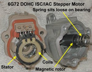
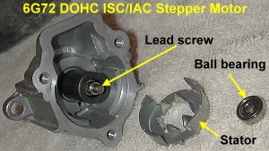
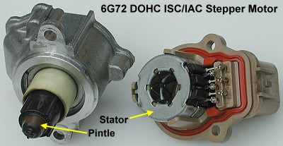
 As shown in the configuration diagram to the right, the ISC servo is located on the throttle body assembly. It shares the by-pass air passages with the fast-idle air valve. Air is drawn through slots "before" the throttle plate, whether the plate is open or closed, and flows into the throttle body "after" the throttle plate. The ISC servo consists of a stepper-type motor and pintle. The motor has two stators, with two coils attached to each, and a cylindrical magnetic rotor, with alternating north and south magnetized strips along its length. Through the middle of the rotor is a lead screw that threads into the body of the ISC servo. The pintle is attached to the lead screw. When the four coils of the motor are energized in particular sequence, the rotor rotates 15º one way extending the pintle one step. When the coils are energized in the reverse sequence the rotor rotates in the oppposite direction 15º and retracts the pintle one step. Extending the pintle reduces the air flow going around the throttle plate, and retracting the pintle increases the air flow. Details concerning the design and operation of the ISC servo are in the 1990 Laser Technical Information Manual (Chrysler Motors publication 81-699-9002).
When the engine coolant is cold, the ISC step count is close to 100 (retracted). As the coolant warms, the ECU gradually reduces the step count to about 10 (extended). This can be observed using a MUT or datalogger. I rarely see the step count reach 0 on a datalog. The ECU will increase steps to adjust idle speed or to allow additional air through the throttle body for the reasons listed above. ISC step count often increases at higher cruise speeds and during WOT operation. When the ECU is placed in "basic idle speed adjustment mode", by grounding the ignition timing adjustment terminal and the selected terminal in the diagnostic connector, the ISC servo is adjusted to the preset warm-idle position (9 steps plus altitude compensation; at ~5600' ASL my ISC goes to 13 steps).
If the stepping motor in the ISC servo malfunctions, idle quality problems usually result. These problems can include unstable idle speed, high idle speed, and stalling. Stalling also may be experienced when shifting or when decelerating. This servo wears out over time (maybe between 50,000 and 100,00 miles?). If the internal coils are partially or completely shorted (that is, if low resistance is measured across the coils), it is possible that the ECU/ECM can be damaged. Current comes from the MFI relay (after a 20-A fuse) and grounds in the ECU; the ECU is not well protected from excess current in case of a short or partial short inside the servo.
If you suspect the ISC servo is bad, I suggest troubleshooting the device before replacing it. The service manual describes several tests. I describe one of these, testing the resistance of the four coils, in a section below. A thorough cleaning, also described below, may improve ISC servo functioning.
If you decide to replace it, Tallahassee Mitsubishi (FL, 1-888-825-5648) lists the ISC servo (part number MD628053) for $329.93 and sells it over the phone for a discount price of about $247 (July 2006). The same ISC servo (MD628053) is used on all Stealth and 3000GT models (SOHC, DOHC, DOHC turbo), as well as most DSM models and the Mitsubishi Galant (basically Mitsubishi/DSM cars that use the 4G63, 4G64, or 6G72 engines).
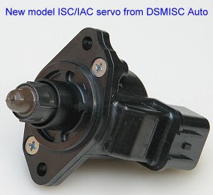
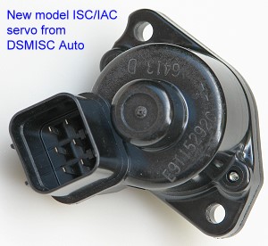
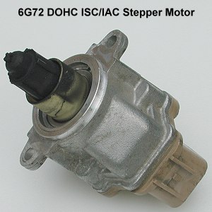
http://www.dsmisc.com/ recently opened (July 3, 2006) and sells brand new Mitsubishi (the Mitsubishi logo is molded into the housing along with part number E9T15292C) ISC/IAC servo motors for $129.75 (a price that can't be beat for a brand new part! In fact, I bought one.). Note that these newer servo motors are improved over the older models and the coils test at ~40 ohms rather than the 28-33 ohms of the original and older servo motors. The ISC/IAC servo I bought from DSMISC Auto had resistance values of 39.7 (1,2), 39.7 (2,3), 40.1 (4,5), and 39.7 (5,6) ohms. DSMISC Automotive also has a web page describing problems with the ISC and some testing tips (see their FAQ page). As the pictures below show, the design of this updated servo is slightly different than that of the original servo. I installed this ISC servo and it works perfectly, including some of my idle problems. 3000GT owners Patrick S. and John L. recently (2007) emailed me to let me know they installed one and it fixed their idle problems and has been working great. Both were impressed doing business with DSMISC Automotive.
Auto Computer Supply (ECM-ToGo) (888-326-8646, Houston, TX) sells Mitsubishi ISC servo motors for about $145 (July 2006). Give them a call for current pricing and availability. ECM-ToGO also has a web page for diagnosing ISC/IAC servo failure.
Foreign Auto Computer (800-241-6689, Tampa, FL) rebuilds and stocks Mitsubishi ISC motors for our engines. They offer an 18-month warranty. Give them a call for pricing and availability.
www.3si.org member SMTCapeCod provided the following tip. Our ISC servo is manufactured by Standard Motor Products, Inc. It is part #AC99. He paid $143 for a new one at Rock Auto. It has a black cover instead of a biege one. Go to http://www.rockauto.com/, select your year and model Mitsubishi car, and enter AC99 in their parts search text box near the upper right corner.
These instructions supplement the service manual's instructions for removing and installing the ISC servo. I provide some additional tips regarding cleaning. Please read all of these instructions before beginning this operation. The suggested tools include: a Phillips screwdriver, an 8-mm socket with 6" extension and wrench, tools required to remove the battery from its tray and the Y-pipe from the throttle body, a bench vice and a hand impact tool (eg. Craftsman part number 47634, 47763, or 47762, ~$20), a toothbrush (or similar tool), electrical parts cleaner (eg. CRC Lectra-Motive Electric Parts Cleaner part number 05018), safety glasses, and a spray lubricant (eg. Bel-Ray 6 in 1, or any thin-film silicon or "moly" lubricant that will not harm electrical contacts).
Removal
1. Battery and Y-pipe. With the ignition off, remove the negative battery cable from the battery. Be sure you have security codes for any devices that might need them before you do this. Remove the battery. If you cannot easily get access to the ISC servo with the just battery removed, disconnect the Y-pipe from the throttle body and move it out of the way or remove it altogether. I tied my aftermarket braid-protected fuel lines out of the way. I don't think the stock lines are in the way.
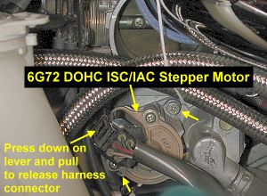
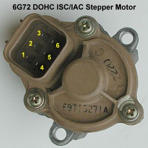
2. ISC servo. Press down on the release lever of the wiring harness connector and pull it off the ISC servo. You may have to wiggle it a little as you pull. Do not pull on the wires. At this point you can test the resistance of the four coils or wait until you have the ISC servo off the throttle body. To perform this test, measure the resistance between terminals 2 and 1, between 2 and 3, between 5 and 4, and between 5 and 6. The resistance should be in the range of 28 to 33 ohms for the original and older models, and ~40 ohms for the most recent model, which is after our 3S cars were manufactured (see http://www.dsmisc.com/). The results for me were 30.1, 30.1, 30.3, and 30.4 (same order as given above) with the ISC servo off the throttle body.
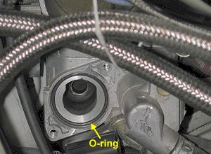
Using a socket and wrench, remove the two 8-mm screws, indicated by the shortest arrows in the picture below, which attach the ISC servo to the throttle body. A Phillips screwdriver can be used but is not recommended. Be careful to not drop the screws as you remove them. One of the screws (lower left) was missing on my ISC servo. The replacement is a M5x0.8 metric screw that is 15mm or 20 mm long. Pull the ISC servo out of the throttle body. Inspect the o-ring to be sure it is still in place and in good shape. As the picture below shows, the pintle had a bit of carbon deposited on it. I would guess this is from the exhaust gas recirculation (EGR) system. With the two pieces of the servo separated (see next section), the inside components looked clean and new.
Inspection and Cleaning
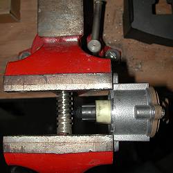
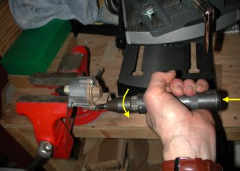
1. Separate ISC servo pieces. If you do not want to inspect or clean the inside of the servo, go to step 2. Three Phillips screws must be removed to separate the two halves of the servo. These were on fairly tight. I did not want to risk stripping the heads, so I used a hand impact tool to loosen the screws. I placed the servo in a bench vice as shown below. The impact tool is adjusted for loosening and a Phillips socket is inserted. Grasp the tool with one hand and apply pressure into the screw and counterclockwise. Strike the end of the tool with a hammer. Each screw loosened up. After removing the servo from the vice, I finished removing the screws with a screwdriver. The pictures below show what the servo looked like when I opened it up and before cleaning it. The spring sits loosely on the roller bearing; be sure you don't loose it as you separate the halves. One of the stators slid off the coils and remained with the rotor section. I pulled the stator out with a forceps and put it back on the coils, using the notch to line it up correctly.
2. Clean the ISC servo and reassemble. I used the electrical parts cleaner, an old toothbrush, and a soft rag to clean the pintle. I also sprayed the insides with cleaner and wiped out what I could. After the parts are dry, inspect the red gasket that seals the two halves of the servo. Gently push it into its groove if necessary. Before putting the two halves together, I rotated the lead screw so that the pintle was in the middle of its range of motion. I am not sure if this accomplished anything positive or not. I suspect the ECU tests the servo by retracting and extending the pintle to correctly index the steps. I placed the spring on top of the ball bearing and slid the coil section onto the rotor section. Insert and start each of the three screws by hand. Tighten with a screwdriver. I did not use the impact tool to torque the screws.
Installation
Installation is basically just the reverse of the removal steps. I wiped clean the cavity of the throttle body where the servo inserts using my bare fingers, not wanting to risk leaving any pieces of cloth behind. Insert the pintle into the throttle body, aligning the mounting holes with the harness connection positioned to the upper left. The upper right screw is easy to start by hand using a socket and extension (no wrench yet). The lower left screw may be harder to get started. I take a piece of masking tape and place the sticky side against the head of the screw, I then insert the screw into the socket, twisting and wrapping the masking tape around the outside of the socket. This way the screw does not fall out of the socket as I start it by hand. Once the two screws are started several turns, use the socket wrench to finish tightening them. Reconnect the electrical harness, being sure it snaps into place. Replace the Y-pipe if moved and the battery. Connect the negative battery cable last.
Start the engine and perform the basic idle speed adjustment procedure (see the service manual) if necessary after the engine and coolant have warmed up.
Page last updated january 19, 2009.