MSD 8.5mm Super Conductor Ignition Wires
Installation for the Mitsubishi 3000GT and Dodge Stealth
by Jeff Lucius
Introduction
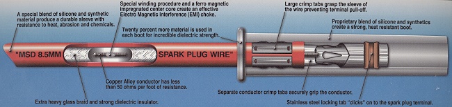
Ignition wires have four tasks to accomplish: (1) conduct as much of the high-voltage, low-current ignition energy as possible, (2) insulate this energy from metallic and electronic components of the engine, (3) protect the conductor from heat, abrasion, and chemicals, and (4) suppress ignition-generated electromagnetic interference (EMI). Maximum ignition energy is transferred from the coil to the spark plug with the least amount of electrical resistance and the greatest insulating ability (highest dielectric strength). Insulation against voltage arcing or leakage, heat, abrasion, and chemicals is accomplished using an 8-mm or larger diameter sleeve made of special blends of silicone and synthetic material. EMI suppression is accomplished either using higher resistance wires and/or a fine copper-alloy wire spirally wound around a ferro-magnetic impregnated center core. Spiral-wound wires, along with a 0.5" to 1.0" separation between wires, help to reduce induction crossfire between ignition wires.
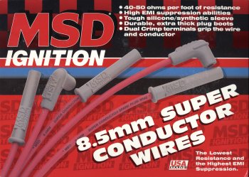 This web page shows how to install the MSD Ignition universal 8.5mm Super Conductor Wire Set (part numbers 31199 or 31179) on the DOHC 6G72 engine in the Mitsubishi 3000GT and Dodge Stealth. MSD Ignition provides excellent instructions with these "universal" fit, 8-wire or 6-wire kits. You may want to use MSD ignition wires if you have determined that the ignition wires should be replaced (the service manual recommends replacing them every 5 years or 60,000 miles), you want to install a high-performance ignition wire set, or you just want a custom look for your engine compartment.
I bought this set (for 8-cylinder engines) from Summit Racing for $75.95 (Summit part number MSD-31199). Summit also sells a universal kit for 6-cylinder engines for $73.39 (Summit part number MSD-31179). Both kits use multi-angle spark plug boots and include socket-style terminals and boots for our coils as well as HEI-style terminals and boots. MSD also provides custom fit red 8.5mm Super Conductor 6-wire sets for the DOHC 6G72 (3000GT, Stealth, Diamante), part number 32709 (available for $91.39 at Summit Racing). However, there were some fitment issues with the original "custom fit" set; the wires are too long. In October 2003, MSD Ignition began marketing a revised wire set. These wires are closer to stock lengths, but several individual wires are still longer than stock. The custom fit set (32709) do not use the multi-angle plug boots. Instead they use plug boots that fit just like the stock plug boots.
For price comparison, Tallahassee Mitsubishi sells the factory spark plug cable set at the (over the phone, 888-825-5648) discount price of ~$58.78 for MD156560 (1991-1992 models), ~$54.04 for MD193980 (1993-1997 models), or ~$70.51 for MD347620 (1998-1999 models).
When I had my 1992 Dodge Stealth TT engine rebuilt in 1997 I replaced the 54,000-mile, 5-year old factory wires with a set of pre-fitted Magnecor KV85 V5 8.5 mm ignition wires. At the time I thought all ignition wires were the same and the red color of the Magnecor wires dressed up the engine bay a little. Fast forward to 2003 and 10,000 miles on the new engine and I was having problems with spark misfire. Using my timing light I saw an irregular strobe and incorrect rpm values. The timing light's rpm display showed ~1400 much of the time (our wasted spark ignition system) with some ~700 values (spark plug misfires). I installed new copper core NGK plugs (BCPR6ES-11 gapped at 0.040"), new factory ignition coils, a new factory power transistor unit, and, because it had been 6 years since I changed the wires, new wires. This cured the spark misfires at idle, which can be a problem if trying to pass emissions tests. The misfires were likely due to the old, worn-out coils on my engine. While the very-high resistance in the Magnecor wires probably did not cause the problem, they did not help to alleviate it either. [Just as a FYI, I am running 17 psi boost to 7300 rpm (redline) with NGK BCPR6ES-11 gapped at 0.040", these MSD wires, and new factory coils and PTU, and am not detecting any spark misfires.]
There is nothing inherently bad about high-resistance wires as long as the available voltage always exceeds required voltage under all engine operating conditions. In fact, high-resistance wires (or rather high-resistance in the secondary circuit, which would include the 4000-5000 ohm resistor in a resistor-type spark plug) minimizes radio-frequency and other electromagnetic emissions from the circuit. However, when operating the ignition system at its limits, that is, when the most voltage is required at the spark plug gap (such as at very high boost pressures), the 100s to 1000s of volts lost to high-resistance plug wires may cause misfires.
I decided to not use Magnecor wires again because of the high resistance I measured in the wires. Magnecor argues on their web page http://www.magnecor.com/magnecor1/truth.htm that measuring resistance with a volt-ohm meter is irrelevant and that "skin effect" electrical transmission occurs when current is in the ignition wires. What Magnecor fails to mention is that when skin effect transmission is occurring, then the effective resistance along the wire actually increases because current is restricted to near the surface of the conductor and so there is less cross-sectional area for current (thus increasing effective resistance).
However, when spark is occuring, voltage is relatively constant and there is no alternating current in the plug wires and so skin effect is irrelevant. Before the spark, as voltage is rapidly increasing to that required to cause a spark, there is no current at all! What happens after the spark is irrelevant as far as misfires are concerned (in fact, AC-like variations in voltage occur as there is a resonant energy transfer between capacitance and inductance in the coil's secondary and primary windings as remaining emf in the circuit is dissipated).
In a series circuit, such as in the High Tension side of our coils (2-ignitionsystem.htm) when spark is occuring, voltage drop across each resistor in the circuit is directly related to resistance. Higher resistance means a greater voltage drop across the resistor. Outside of the coil, the resistors are both ignition wires, both spark plugs when they are resistor plugs, both spark plug gaps, and the engine heads and block. The sum of all the voltage drops must equal the voltage available in the electric field produced in the High Tension circuit.
So, DC resistance measured along the ignition wire's length does matter. As confirmation of this, Bosch's book Gasoline-engine management, 1st edition states on page 59 "It is important to remember that higher levels of resistance in the secondary circuit are synonymous with corresponding energy loss in the ignition circuit, and result in a reduction in the energy available for firing the spark plug." The greatest amount of voltage is available at the spark plug gaps by minimizing the resistance in the secondary circuit. This can be accomplished by using wires with the lowest DC resistance and using non-resistor spark plugs. Usually, the problem with low resistance wires (and non-resistor plugs) is that they can do a poor job of suppressing EMI generated by the ignition system. MSD Ignition, Accel, and other manufacturers, have minimized this problem with careful design. I hear no ignition noise through my Stealth's radio (FM or AM).
The table below shows the resistances I measured for the new MSD wires, for the factory wires that were on my engine for 5 years and about 54,000 miles, and for the Magnecor wires that were on my engine for 6 years and about 10,000 miles. I measured the approximate wire length in inches between the tops of the two boots. However, the resistance is measured from the end of each terminal.
| Comparison of Ignition Wire Resistances |
| |
MSD 8.5mm Super Conductor |
Factory MD156560 |
Magnecor KV85 V5 |
| Cyl # |
Ohms |
Length
(inches) |
Ohms
per ft |
Ohms |
Length
(inches) |
Ohms
per ft |
Ohms |
Length
(inches) |
Ohms
per ft |
| 1 |
131 |
~16 |
98 |
5810 |
16 |
4358 |
8720 |
16 |
6540 |
| 2 |
124 |
~31 |
48 |
7480 |
29 |
3095 |
16070 |
30 |
6428 |
| 3 |
51 |
~11 |
56 |
3975 |
11 |
4336 |
6700 |
10.5 |
7657 |
| 4 |
105 |
~25 |
50 |
7070 |
24.5 |
3462 |
13920 |
24.5 |
6818 |
| 5 |
35 |
~7 |
60 |
3310 |
6.5 |
6110 |
4770 |
6.5 |
8806 |
| 6 |
104 |
~25 |
50 |
8060 |
23.5 |
4116 |
13380 |
26 |
6175 |
The resistance for the #1 cylinder MSD wire is a bit high for its length. This is the first MSD wire I built so I may not have done the best job crimping the coil-end terminal. Regardless, the resistance for MSD ignition wires is much less than for the factory or Magnecor wires. Theoretically, this means much more energy can reach the spark plugs using the MSD wires. Practically, conductance in ignition wires is more complicated than just ohms/ft; it involves careful selection of conductor material, spiral design, and core material to optimize capacitance, inductance, and resistance for maximum spark energy. Nevertheless, with these new MSD wires, new NGK BCPR6ES-11 spark plugs gapped at 0.040", and new factory coils, I am not getting spark blowout (misfires) at 15.5 psi boost to 7000 rpm (I have not increased boost higher because of knock).
Even though this web page describes my installation of the MSD ignition wires, the tips and instructions could be used to install other "universal" wires sets, such as Moroso's Ultra 40 (40 ohms/ft), or pre-fitted wire sets, such as
- MSD Ignition 8.5mm Super Conductor (40-50 ohms/ft)
- Accel Thundersport (150 ohms/ft)
- Taylor 8mm Spiro Pro (350 ohm/ft)
- Aurora ignition wire set (400 ohms/ft)
- Vitek Performance Cables (their web site does not mention resistance, but John Monnin measured them at about 800 ohms/ft; the label under Vitek's braiding says "Magstar Gold 8mm High Performance S-4 Stainless Steel Mag Wire" - thanks John!; Magstar wires are manufactured by Wiretec)
- Wiretec Magstar Gold (800 ohms/ft as measured by John Monnin)
- NGK Resistor Spark Plug Wire Set (2600 ohms/ft)
- Mitsubishi factory wire sets (3000++ ohms/ft)
- Car Quest brand wire sets (3000++ ohms/ft - Thanks to Bret for measuring these wires.)
- Magnecor KV85 (6000++ ohms/ft)
Before installing any aftermarket replacement wires for our engines, be sure to measure the resistance. If the resistance is higher than the factory wires, like the Magnecor wires are, I recommend against using that brand of ignition wire unless there is a special demand for EMI suppression that low-resistance wires cannot provide.
I invite any 3000GT/Stealth owner that is installing new ignition wires (factory or aftermarket) to measure the resistance between the two terminals and send an email to website at stealth316 dot com with the results. I will compile the information and either update this web page or make a new technical short note on this subject.
I have recieved these measurements from owner Fast Eddie for the MSD 8.5mm Super Conductor wire sets custom built by Import Power Online: ohms/ft - 37.5, 40.5, 42.2, 42, 36.5, 42.
Please read all of these instructions before beginning this operation. The suggested tools include: 10, 12, and 13 mm sockets and driver, 5/8" spark plug socket (with a rubber insert to grasp the plug), a flexible socket extension (like a little universal joint), 3" and 6" socket extensions, screwdrivers, some wire, regular pliers, long needle nose pliers, forceps, a torque wrench, a pencil (to mark the MSD wires), utility knife, a volt-ohm meter (to measure resistance in the wires), a 3-1/2" or larger bench vise, and engine degreaser (to clean the plenum, intake manifold, gaskets, and throttle body).
Plenum Removal
These instructions are basically the same as those for replacing the spark plugs except here we want to remove the plenum from the engine and throttle body. Of course, now would be a good time to replace the plugs (2-sparkchange.htm).
1. Battery. Disconnect the battery negative terminal (10 mm). This is optional but it is preferred for safety. If your radio has security codes, be sure you have them before disconnecting the battery.
2. Throttle body. Remove the four 12-mm bolts that attach the throttle body to the plenum and remove the gasket. The gasket is part number MD180361 for all DOHC 6G72 engines. You should be able to re-use the gasket. The gasket is plastic coated flexible metal and the small tab goes on the top and to the rear. Clean the gasket with degreaser if necessary.
3. Rear IC pipe and heat shield. Remove the rear intercooler pipe and stuff a clean rag into the top of the turbo and the open end of the IC pipe. Take off the O-ring and wipe it clean with a rag. Later, before installation, you should apply a little high temperature grease to it. Replace it with a new one if it is damaged or worn. The part number is MD090788 (O-ring, eng air intake line). My engine is missing the heat shield associated with this IC pipe so remove the shield if necessary.
4. Accelerator cable bracket. Note the tension of the cable and/or the location of the bolts in the bracket for the installation later. Remove the accelerator cable bracket (two 10 mm bolts) and set aside.
5. Vacuum hoses. The large clutch boost hose is on the driver's side of the plenum. The large brake booster hose is on the back of the plenum near the throttle body. The fuel pressure regulator (FPR) hose is a smaller hose on the back of the plenum near the throttle body. The bypass valve (BOV) hose is a smaller hose on the front of the plenum near the throttle body. Remove each of these hoses. Pinch the clamp and slide it down the hose an inch or so. Grasp the hose, twisting slightly if needed to break it free, and pull it off the plenum.
6. Oil supply line bracket. Remove the bolt (12 mm) holding the oil supply line near the rear turbo for more working space.
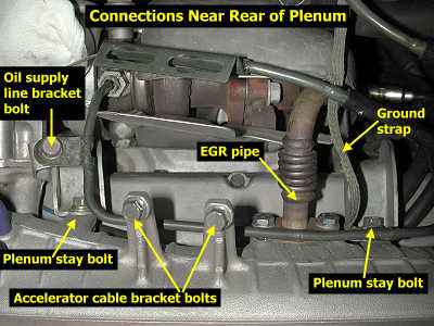
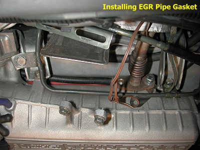
7. EGR pipe. Remove the passenger-side screw (12 or 13 mm) from the EGR pipe (it comes up from the rear cat near the oxygen sensor). Loosen (but do not remove) the driver-side EGR pipe screw, and slide the metal gasket downward (or upward). Securely attach a wire to the gasket (forceps can help with this) and then remove the remaining EGR pipe screw. You may need to pry the pipe away from the plenum a little with a slotted screwdriver or similar tool. Set the gasket aside if it can be re-used. This gasket is part number MD149764 for all DOHC 6G72 engines. The screws are M8x1.25mm and 20 mm long (threaded section below head).
8. Rear plenum stays. Carefully remove the two screws (12 mm) attaching the rear of the plenum to the stays (brackets). Note that a ground strap attaches to the driver's side stay. These screws are also M8x1.25mm and 20 mm long. The ones on my engine had captured washers and were thread cutting machine screws.
9. 3-plug bracket and fuel injector harness. Remove the two (10 mm) bolts that hold the 3-plug bracket on the passenger's side of the plenum. Remove the two (10 mm) bolts holding the fuel injector harness to the plenum.
10. Front plenum bolts/nuts. Remove the three (12 mm) bolts from the plenum front, the two long (12 mm) bolts from the plenum top, and the two (12 mm) nuts from the plenum front sides. The plenum may pop a little with the release of pressure.
11. Plenum. Lift the plenum straight up to clear the front studs, then set it aside. Remove the gasket. The gasket is plastic coated flexible metal and the small tab goes on the driver's side. Unless the gasket is damaged, use a degreaser to clean it and set it aside to be used again. This gasket is part number MD143791 for all DOHC 6G72 engines. Cover the intake manifold with a clean rag. You definitely do NOT want anything falling in there.
You can take this opportunity to remove the carbon buildup inside the throttle body and plenum. Do not spray degreaser in the throttle body; the service manual warns against allowing solvents to enter the air cavity that connects to the ISC/IAC servo and FIAV. Apply the degreaser to a rag or Q-tip and use this to clean the throttle body.
Wire Set Installation
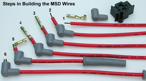
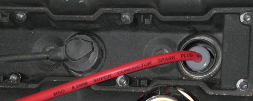
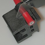
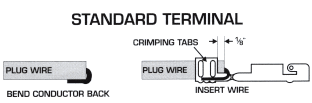
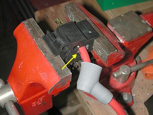
Follow the installation instructions provided by MSD. The plug end of the wire is finished and there is nothing to do at that end. The wire at the plug boot end just bends over. Because these are "universal" wire replacements, the MSD plug boots do not seal the spark plug well. It will be necessary to vacuum or blow out the well before removing the wires in the future. For attaching the wire to our factory coils, only the copper-colored standard (90º) socket-style terminal (not either of the silver-colored dual crimp terminals) and only the boot with the larger opening will work. MSD supplies a mini-stripper-crimper tool, shown in the upper right of the picture below. The basic steps to building the wire are as follows and illustrated in the picture below.
1. Attach wire to plug and layout wire to the coil. Measure for length and strip.
2. Slide wire through coil terminal boot.
3. Bend conductor and attach terminal.
4. Crimp terminal.
5. Bend terminal 90º.
6. Pull terminal back into boot.
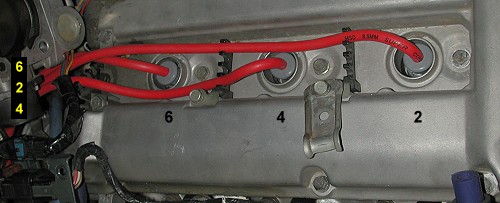
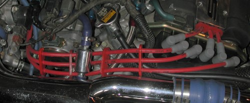
1. Layout wires, mark for length, and strip end. The front wires are fairly easy to figure out. So I will focus on building and laying out the back wires. Go ahead and remove all the old ignition wires. Attach the new MSD wires to the back plugs and arrange as shown below. You will feel the terminal "click" onto the spark plug when it is attached to the plug correctly. The #2 wire will cross the #6 wire near the #6 plug well. This is how the service manual shows to route the cables. Arrange the rear cables as shown in the order 6-2-4 so that they do not need to cross again to attach to the coils. I was not able to push these cables into the wire separator closest to plug #6 (to the left of the well in the picture but not visible). However, I was able to push the wires into the next separator a few inches farther away. Do not route the wires too tight. On the other hand do not make them too loose.
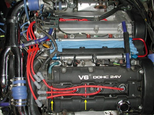
Place the boots on the coils. Use a pencil to mark the wires for length. I marked the middle of the coil boot "head" as shown by the yellow arrows. Remove the wires and start work with the longest one, the #2 plug. If you mess this one up, you can cut it shorter and use it on any of 5 other plugs. And because there are 8 wires in this set, you have two spares if you need them.
The length you marked the wires will be the end of the sleeve in the boot. The wire itself will have to be 5/8" longer. I made a second pencil mark 5/8" past the first one. You can see both marks in the left picture below. Cut the wire with the utility knife at the second mark. Slide the wire into the stripper tool as shown. Lay a utility knife across the wire and press down. The stripper is designed so that you will be cutting only through the sleeve and not the conductor. Holding the knife steady and flush against the guide, rotate the wire until you feel the sleeve break loose. Slide the 5/8" piece of sleeve off the wire as you rotate it counterclockwise. If you want (I did), first practice with the piece of wire you cut off earlier.
2. Slide wire through coil terminal boot. Remove the boot from the coil. Slide the wire through the boot as shown here in the pictures. MSD suggests using dielectric grease to make this easier. I had no problem sliding the cable through without grease. If you want, keep the markings on the wire aligned with the top of the boot.
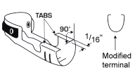
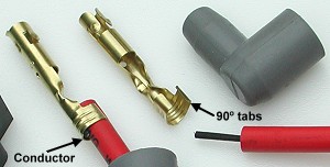
3. Attach terminal. Using pliers, make the 1/16" crimping tabs as shown below. Fold the conductor over as shown and slide the wire into the terminal so that about 1/8" extends past the end of the crimp tabs. Compress the crimp area a little around the wire with pliers. You will need to shape the crimp area so that the crimping tool will barely slide onto it. You will see what I mean as you perform the next step.
4. Crimp terminal. Place the terminal in the "left" half of the crimping tool. The exposed conductor should be positioned as shown by the arrow in the picture below. Place the "right" half of the tool on the terminal. Place this assembly in the bench vise. Tighten the vise a little and be sure that the crimping tabs are symmetrically located in the tool. Tighten the vise until you see the sleeve fill the opening in the tool. Loosen the vise and check the terminal. You should not be able to pull the wire out of the terminal when exerting moderate force. If the wire slips out, open the crimping tabs a little and start over.
5. Bend terminal 90º. Carefully bend the terminal into a 90º angle.
6. Pull terminal back into boot. Grasping the wire, pull the terminal back into the boot until the angle rests against the top of the boot.
That is all there is to it. Measure the resistance connecting the VOM leads to each terminal. You should have about 50 ohms per foot or less of resistance. This first wire may take you 5 to 20 minutes to build. The last ones will probably only take you one minute. Repeat steps 2 through 6 for the rest of the wires.
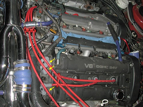
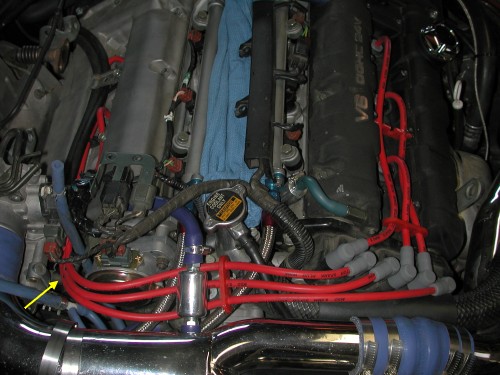
7. Install wires. Install the wires being sure you connect the spark plugs to the correct coils. The MSD boots will "click" into place when they are attached correctly to the spark plugs. The cylinder numbers are stamped into the stock coil mounting bracket. The front (right) bank cylinders are numbered 1, 3, 5 with #1 at the front (timing belt side) of the engine. Rear (left) bank cylinders are numbered 2, 4, 6 with #2 at the front of the engine. Try to route the wires so there is always about 0.5" of space between them. Aftermarket wire separators help with this. I was able to re-use the factory separators between spark plug wells on the rear bank. However, I used aftermarket ones on the front bank (shown by the yellow arrows in the upper picture below). For the separator between cylinders #3 and #5 I used the utility knife to slice off the edges of the "fingers" so that the plug wire cover would go back on. The yellow arrow in the lower picture shows the location of the factory separator (connected to the engine by a bracket) I was able to use. Double check that all wires are correctly and securely connected to the spark plugs.
Plenum Installation
1. Manifold-plenum gasket. Remove the rag covering the manifold. Clean the mating surfaces of the manifold and plenum with an engine cleaner or degreaser and then wipe dry with a clean cloth. Install the new plenum gasket or the old one that has been cleaned and is free of oil and dirt. The protrusion goes to front of the engine, that is, the driver's side of the manifold. Lower the plenum onto the manifold studs. Do NOT attach bolts or nuts at this time. You will need the plenum loose for the next step.
2. Rear stays. Bolt the plenum to the rear two stays first. You may need to apply your weight or tap the plenum with your fist or rubber mallet to get the holes to line up. I sometimes get up on the engine with my knees on the plenum (using a rag or kneeling pad) to apply pressure. Be sure to re-attach the grounding cable and oil pipe bracket with the driver-side stay. Insert the two bolts by hand. Be sure you can turn the bolts several revolutions by hand to avoid stripping the soft aluminum threads in the plenum. Torque to 18 N-m (13 ft-lbs).
3. EGR pipe. With a wire attached to the new EGR pipe gasket, insert the driver-side bolt through the EGR pipe and gasket and into the plenum. Tighten a little by hand. Remove the wire, slide the gasket around, and insert the other bolt. The bolts can now be tightened (18 N-m; 13 ft-lbs).
4. Oil supply line bracket. Start the bolt by hand several turns then finish with a socket and ratchet.
5. Front plenum bolts/nuts. Install the front five plenum bolts and two nuts. Torque them all to 18 N-m (13 ft-lbs). As always, start the bolts by hand several turns to minimize the chances for stripping the threads.
6. Vacuum hoses. Slide the hoses (clutch booster, brake booster, FPR, and bypass valve) onto the plenum at their respective nipples, and slide the clamp to the end of each hose.
7. Accelerator cable bracket. Re-attach the bracket. Adjust the tension on the cable so that the throttle plate is closed completely (same for the dashpot) and with very little extra slack in the cable. The engine control module sets the engine idle speed using the idle speed control (ISC) stepper motor, so the throttle cable must not be applying torque (rotating force) to the throttle plate. However, too-loose a cable will result in delayed throttle response and the throttle plate may not open completely.
8. 3-plug bracket and fuel injector harness. Re-attach these components. Be sure to check the fuel pressure regulator hose and the other vacuum hoses.
9. IC pipe. Remove the rags from the top of the rear turbo and the IC pipe. After applying a small amount of high-temperature grease to the o-ring, install the rear IC pipe.
10. Throttle body. Being sure the mating surfaces and gasket are clean, bolt the throttle body to the plenum (gasket tab goes up and to the back). Bolt the throttle body to its stay if you want (I leave this bolt off).
11. Battery. Re-attach the negative battery cable to the battery. The disconnected battery will reset the ECM. Let the car idle a few minutes and check for leaks or other problems.
Page last updated January 18, 2005.