Oil Pan Removal on the
AWD Mitsubishi 3000GT/Dodge Stealth
by Jeff Lucius
Introduction
These instructions describe how to remove the oil pan on the turbocharged version of the DOHC 6G72 V6 found in the Dodge Stealth and Mitsubishi 3000GT. There are not too many reasons that you would want to remove the oil pan while the engine is still in the car. The few that I can think of are 1) repair the sealant between oil pan and block, 2) inspect the rod bearings, 3) repair the drain plug threads, and 4) flatten the bottom of the oil pan if it has been dented or creased.
Read all of the instructions and look at the pictures before you begin. You will need to raise and support the front of the car. I have some instructions for doing this at this link 2-raisecar.htm. The tools required are a socket wrench with 10-mm, 12-mm, 14-mm, 17-mm, and 19-mm sockets and some extensions, #2 Phillips screwdriver, a pry bar, and some "RTV" sealant. You may also want to use new gaskets for where the oil return tubes attach to the oil pan (two of MR258477) and for the downpipe (two of MB687002). You may want to keep common parts together in labelled containers or bags.
Pre-removal
1. Battery. Disconnect the negative battery terminal. Be sure you have the security codes for any device that might need them (like some stereos).
2. Raise car. Get the front of the car securely off the ground so that you can safely work under the car.
3. Drain oil. Drain the engine oil.
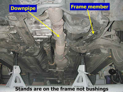
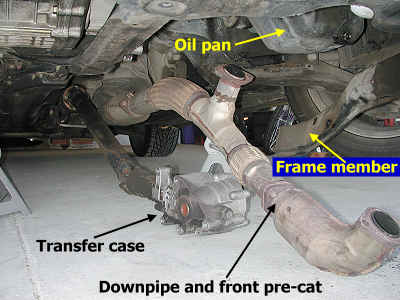
4. Frame member. Remove enough of the plastic cover bolts (or the entire covers) under the engine so that you can remove the six 14-mm bolts attaching the frame member on the driver's side of the car. The frame member is also attached to the wheel well cover. You can disconnect this grommet or let the member hang attached to the grommet.
5. Downpipe. Remove the two 19-mm nuts that attach the front pre-cat to the front exhaust fittings and the two 19-mm nuts that attached the downpipe to the rear exhaust fitting. Air tools could be useful if these nuts are stubborn. You will have to partially remove the plastic cover that blocks access to the front two bolts. Let the downpipe rest on the floor. You may have to remove the brace that goes under the main catalytic converter.
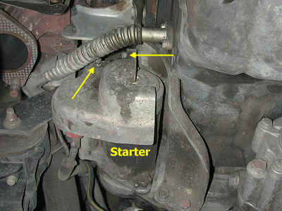
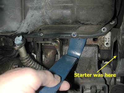
6. Starter. Remove the two 10-mm bolts that attach the protective plate over the starter. Slide the cover out and off. Disconnect the electrical wires to the magnetic switch. Press the release on the connector to remove the smaller wire. Remove the two 12-mm nuts that hold the larger wires on. Remove the two 14-mm bolts that hold the starter on. Note the engine ground wires that attach to these. Set the starter aside.
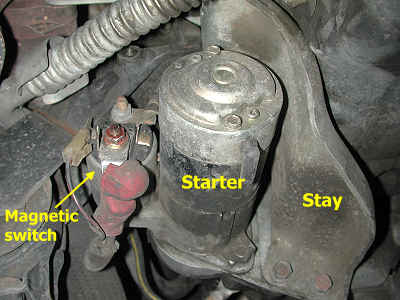
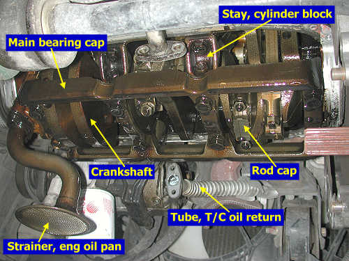
7. Stay. Remove the two 14-mm bolts at the top of the stay and the two 17-mm bolts at the bottom of the stay and set the stay aside.
8. Transfer case. Remove the five 17-mm bolts that attach the transfer case to the transaxle. The front three bolts are about 6" long and the back two are about 3" long. Do not loosen the bolts that hold the cover of the transfer case on. The fluid inside the transfer case cannot leak out at this connection. However, the fluid can leak out of the back of the transfer case if the propeller shaft is removed. You will have to pry the transfer case away from the transaxle with a bar or large screwdriver. When the transfer case is loose, keep the propeller shaft in it and lower the case to the shop floor.
9. Oil return tubes. Remove the two 10-mm bolts that attach each oil return tube to the oil pan. Pull the tubes away from the pan. You may need to put a rag in the end to stop oil from draining out.
Removal
1. Bolts. Remove the 16 10-mm bolts from the oil pan. In case your bolts are rusted or stripped, the part number for these is MD097012 (thanks go to Riyan Mynuddin for this tip).
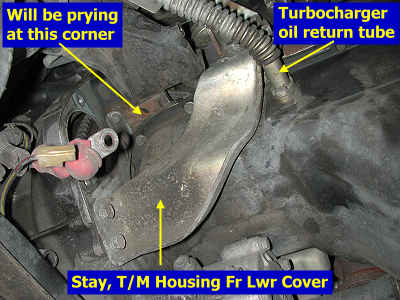
2. Oil pan. The pan is adhered to the block using "RTV" sealant. This seal must be broken to remove the pan. Fortunately, once you get a little bit of the seal broken, the rest breaks free quickly. You can try hitting the pan with a rubber mallet. We pryed one corner loose using a common, household pry bar. The pry bar will probably bend the flange a little, but you can easily straighten that out later.
Installation
1. Prepare surfaces. Drain the remaining oil from the oil pan and wipe it out with rags. Remove all remaining sealant from the flange with a scraper, a wire brush, and gasket remover (we used Permatex Gasket Remover, item #80646). Be sure to flatten the oil pan flange if it needs it. A hard, rubber mallet and a flat surface works well. Again, use paper towels or rags to wipe out the inside of the oil pan. Clean the adhesive and oil off the mating surface for the oil pan on the engine block. Now, before you perform the final cleaning of the mating surfaces, practice installing the oil pan. The output shaft from the transaxle is a small obstacle. After you are confident in how to get the oil pan past the output shaft without touching anything, clean both mating surfaces with a degreaser and dry them off.
2. Sealant. Apply a 4-mm or 0.16" diameter bead of sealant to the oil pan flange as shown in the picture below. The oil pan must be installed withing 15 minutes of applying the sealant. The sealant used is called a form-in-place gasket (FIPG). Bead size, continuity, and placement are critical to guaranty a leak-free joining of parts. The FIPG must be applied evenly and without breaks. Be sure to encircle the bolt holes. Extra sealant can be wiped away before it hardens. The required sealant is a room temperature vulcanization (RTV) type. The RTV hardens as it reacts with the moisture in the atmosphere. Mitsubishi recommends the following RTV sealant: Part No. MD997110. Permatex (Locktite Corp.) lists their Ultra Gray Gasket Maker (P/N 82194, 3.5 oz tube on card) as the OEM equivalent for MD997110 (and for MD997740, the sealant used for the FWD and AWD transaxle cases; Loctite Gasket Eliminator #17430 is also recommended for sealing transaxle cases in the Getrag Service Manual).
3. Bolts. Tighten the flange bolts in the order shown below. Do not over-tighten. The torque is only 6 Nm or 5 ft-lb.
Post-installation
Basically reverse the pre-removal steps above. You may want to use new gaskets where the turbocharger oil return tubes attach to the oil pan. Inspect gaskets where the downpipe and front pre-cat attach to the exhaust fittings and replace them if necessary. The transfer case bolts are torqued to 61-65 ft-lb (85-90 Nm) for 1991-1993 models, and 18-22 ft-lb (25-29 Nm) for 1994+ models. The difference is the 5-speed models have an aluminum case; the 6-speed models have a cast-iron housing. I didn't find torque specifications for the starter bolts. The exhaust nuts should be torqued to 36 ft-lb (50 Nm).
Page last updated February 4, 2005.