Oxygen Sensor Replacement
in the DOHC Mitsubishi 3000GT and Dodge Stealth
by Jeff Lucius
Introduction
 These instructions supplement the instructions in the service manual for replacing the oxygen sensors in the DOHC Mitsubishi 3000GT and Dodge Stealth. The tools and supplies required are a hydraulic jack, jack stands, two wheel chucks (blocks of wood are fine), lug wrench or the appropriate socket and ratchet for your wheels, a torque wrench that goes up to 100 ft-lbs, a small flat-head tool for some Stealth owners to remove the wheel center cap, 10-mm, 12-mm, 14-mm, and 12-mm-deep sockets and ratchet (a swivel head ratchet may be required), 3" and 6" socket extensions, oxygen sensor socket, 2' to 3' breaker bar, pliers, a small amount of anti-sieze lubricant, about six feet of cord, and safety glasses (for working under the car). Please read through all the instructions before starting this procedure. The work below was performed on a 1992 Dodge Stealth R/T Twin Turbo with custom intercooler piping and a front-mount oil cooler.
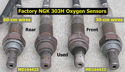
The replacement oxygen sensor must be the same basic type as the original and have the same performance characteristics and heater wattage requirements. The factory replacement oxygen sensors, which include the harness connectors on the ends of the wire, available at the discount Mitsubishi dealers I list on my Garage Page are priced near what you can find "aftermarket" sensors for. I paid $60.92 for each sensor at Tallahassee Mitsubishi (the list price is $81.22; a local Mitsubishi dealer wanted $92, and one local Dodge dealer wanted $120!). The front oxygen sensor is part number MD164422 and the rear sensor is part number MD164423. The wire on the front sensor is 30-cm long and on the rear sensor is 60 cm long. The hex on the sensor is 7/8". The threads are M18 x 1.50mm. The new sensors come with anti-sieze lubricant on the threads. The stock sensors are 4-wire, heated, Zirconia, thimble-type oxygen sensors. Stamped on each sensor is "NGK 303H".
For those of you using other than OEM replacement sensors, here is how the O2 sensor wires are used on my '92 Stealth TT. Terminal assignments on the connector from the sensor as you are looking at the exposed terminals are 1 at upper left, 2 at upper right, 3 at lower left, 4 at lower right.
Black (terminal 1 on connector from sensor) is B+ for the heater
Green (terminal 2, might be a white wire on newer models) is ground for the signal cell in the sensor
Black (terminal 3) is ground for the heater
Yellow (terminal 4, might be a red or blue wire on newer models) is the signal wire (~ 0-1 v)
If using a Bosch O2 sensor replacement, here is how you would splice the wires, using the old O2 harness between the sensor and connector (thanks to Erick, owner of a 1992 Stealth TT, for verifying this).
The two Bosch white wires (for heater) connect to the two black wires. Probably makes no difference which ones.
The Bosch gray wire (ground) connects to the green (or white) wire.
The Bosch black wire (signal) connects to the yellow (or red or blue) wire.
After you have removed the old sensors, compare them to the new ones and inspect them for signs of contamination. These are the first oxygen sensors I have looked at, but it is clear to me in the picture above that the front sensor thimble area looks different than the rear one. Bosch states that "some discoloration is normal, but heavy black deposits indicate an over-rich fuel mixture, dark brown deposits indicate high oil consumption, white or reddish deposits indicate harmful fuel additives, and light colored or grainy deposits indicate a coolant leak."
Pre-Removal for Front Oxygen Sensor
This is probably not what you want to hear, but you will find it much easier to replace the front oxygen sensor if the alternator is removed. You can try skipping the alternator removal steps, but you may not have enough room to use the oxygen sensor socket and ratchet in the very-limited space. Consider this an opportunity to inspect the drive belt for the alternator and AC compressor. I didn't think there was a way to get to the front oxygen sensor from below with the special socket because the AC compressor is in the way. However, an open-end wrench (no special socket) can get to the sensor from below, and fellow 3S owner Shawn told me he changed the front oxygen sensor this way. Another 3S owner, Jed Blanks, was able to get a socket onto the front oxygen sensor with the alternator and AC compressor in place and then used an open-end wrench to loosen the sensor. Give these methods a try before going through the hassle of removing the alternator. Thanks to both gentleman for contacting me. The rear oxygen sensor is much easier to get to.
I should mention that I decided to replace the front oxygen sensor after I removed the AC compressor for repair, which requires the alternator be removed, and the AC condenser for flushing, which requires the radiator fan be removed. The engine had about 62,000 miles and ten years on it so it was time for oxygen sensor replacement. The AC compressor does not need to be removed to replace the oxygen sensor, but the space to work in is very limited. With the AC compressor removed there is plenty of room to work in. It is probably not worth the trouble of dealing with the AC refrigerant and compressor just to change the oxygen sensor. However, if you have the AC compressor and the radiator fan out of the car it is an ideal time to change the front oxygen sensor.
1. Disconnect negative battery cable. With the ignition off, remove the negative battery cable from the battery. Be sure you have security codes for any devices that might need them before you do this. At this point you can try removing parts in the way and then use one of the two techniques mentioned above to loosen the sensor without removing the alternator. If you decide to remove the alternator, then please continue.
2. Lift and support car, remove wheel. You must remove the driver's side front wheel to gain access to the alternator drive belt tensioner. I have some tips for lifting and supporting the car at my web page 2-raisecar.htm and removing the wheel at my web page 2-tirerotation.htm. Generally, you want to loosen the wheel lug nuts a little, lift the car, rest the front cross member near the rear of the control arm on a jack stand, and finish removing the wheel. Be sure the car is securely and safely supported before you proceed.
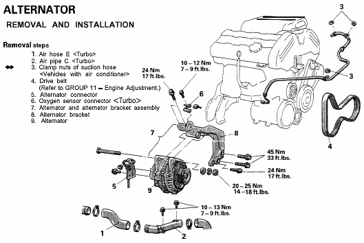
3. I/C pipes. I have aftermarket intercooler pipes and removed enough of the pipes to make access easy to all parts I needed to get to. If you have the stock I/C pipes, remove the pieces as shown in the illustration above from the service manual plus the one that crosses over above the turbo and oxygen sensor. For my setup, I needed to move the suction hose (the next step) first, drain one quart of radiator coolant (an under cover must be removed), and un-attach the front of the top radiator hose. Block the openings in the remaining I/C pipes with rags to prevent objects from entering.
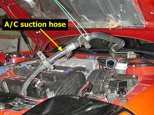
4. A/C suction line. Remove the two 10-mm nuts toward the back, the 12-mm nut on the side, and the 12-mm bolt at the front of the air conditioning suction hose. Lift the hose until it no longer moves easily and tie it off to the hood using a cord.
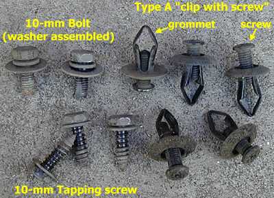
5. Front splash shield. Remove the three tapping screws, the two 10-mm bolts, and the five clips with screws from the plastic splash shield in front of the wheel well. The clips with screws are removed by uncsrewing the screw part a little then pulling the whole clip out. If the screw does not want to back out, then try putting a little upward pressure on the grommet by lightly prying around the base with a small screwdriver.
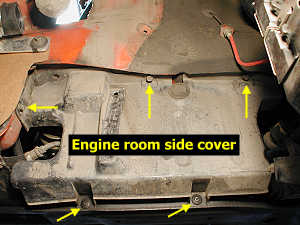
6. Engine room side cover. This cover is behind the driver's side front wheel and conceals the belts and pulleys. Remove the two clips with screws on the bottom and the three 12-mm bolts near the top of the side cover. Set the side cover out of the way.
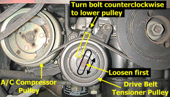
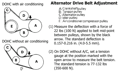
7. Tensioner pulley and drive belt. Before adjusting the tensioner, take a moment to note the tension on the belt between the idler and crankshaft pulleys as shown in the figure at the end of the web page. Loosen, but do not remove, the 14-mm bolt in the center of the tensioner pulley. With a 12-mm socket, rotate the tensioner bolt counterclockwise to lower the pulley and reduce tension on the belt. Stop when the belt is loose enough to remove. Remove the belt and inspect it; replace if old (every 30,000 miles) or if it shows signs of wear. Note how the ridges in the belt fit in the grooves of the different pulleys.
8. A/C condenser fan assembly. The service manual does not mention removing this fan assembly, but you need the extra room when removing the alternator and front oxygen sensor. Mark the two electrical connectors with masking tape next to the condensor fan (the one near the alternator) so you know which goes where. Disconnect the two connectors by pressing on the levers and pulling up. Remove the four 10-mm bolts on the fan assembly and pull the assembly out through the top. The upper mounting "brackets" on the radiator for this fan have sharp corners which could benefit from filing at the edges.
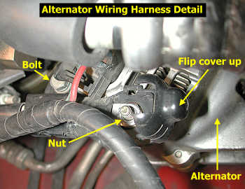
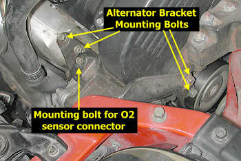
9. Wiring harness connections and brackets. Grasp the bottom of the rounded plastic cover that protects the top cable connection (positive terminal) and raise the cover. Remove the upper 10-mm nut and lower 10-mm bolt, and pull the harness away from the alternator a little. Disconnect the harness completely from the alternator by pressing on the connector lever and pulling the connector away from the alternator. For the turbo models, identify the bolt that attaches the O2 sensor harness connector to the alternator bracket and remove the bolt and O2 bracket.
10. Alternator bracket. Remove the two 14-mm bolts on the driver's side of the bracket (the longer one goes on the bottom). Loosen both 12-mm upper bolts but remove only one. Now support the alternator with one hand as you remove the other bolt. Maneuver the alternator in its bracket up through the top. Two bolts secure the alternator to its bracket.
Front Oxygen Sensor Removal
1. Front heat shield. Remove the three 12-mm bolts that attach the front heat shield. You should be able to get to the front bolts without removing the radiator fan.
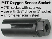
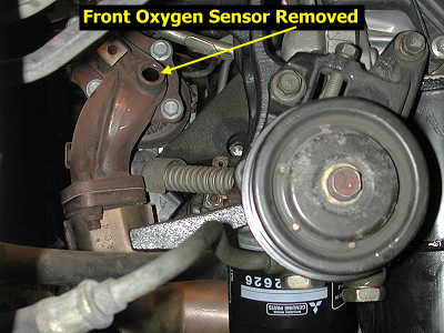
2. Oxygen sensor. As a precaution, you can spray a penetrating oil near the thread area of the oxygen sensor. I did not do this for the front sensor. Fold the oxygen sensor wire down over the sensor and slide the special oxygen sensor socket over the sensor so the wire protrudes through the cutaway. Be sure the socket fits over the hex shell on the sensor. Using an extension and 3/8" ratchet, and probably a breaker bar slid over the ratchet handle, loosen the oxygen sensor. Rotation will be counterclockwise looking from the driver's side of the car, or you will be rotating the breaker bar down from the front of the car. Keep applying pressure on the bar until you hear and feel the sensor break free. Once loosened, you should be able to remove the sensor with light pressure on the ratchet or by turning the extension by hand.
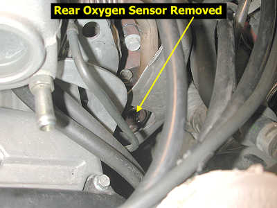
Rear Oxygen Sensor Removal
My engine is missing the top heat shield above the rear turbo. So I do not know if this part needs to be removed to gain access to the rear oxygen sensor. It does not look like it, though.
1. Intercooler pipes.
Remove sections of intercooler pipe so you can get to the rear oxygen sensor. Plug the ends of the remaining exposed pipes with clean rags.
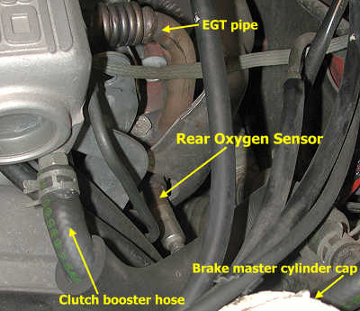
2. Clutch booster air hose. Using pliers slide the hose clamp away from the end of the hose where it attaches to the plenum. Twist the end of the hose a little and pull it away from the plenum. Place or tie the hose out of the way.
3. Throttle cable. I found it convenient to un-attach the throttle cable from the plenum to give my hands better access to the rear oxygen sensor. Note the tension on the cable then remove the two bolts attaching the throttle cable tensioning bracket to the rear of the plenum. Place or tie the cable out of the way.
4. Sensor harness connection. Disconnect the two pieces of the electrical harness, which sits on the front fuel rail. Carefully untangle the oxygen sensor wire and its connector from the other parts around it.
5. Oxygen sensor. As a precaution, you can spray a penetrating oil, such as Aero Kroil, near the thread area of the oxygen sensor. I did this for the rear sensor but not the front one. Fold the oxygen sensor wire down over the sensor and slide the special oxygen sensor socket over the sensor so the wire protrudes through the cutaway. Be sure the socket fits over the hex shell on the sensor. Using a 3/8" ratchet, and probably a breaker bar slid over the ratchet handle, loosen the oxygen sensor. Rotation will be counterclockwise looking from the driver's side of the car, or you will be rotating the breaker bar down from the front of the car. Keep applying pressure on the bar until you hear and feel the sensor break free. Once loosened, you should be able to remove the sensor with light pressure on the ratchet or by turning the extension by hand. You will probably need to keep re-positioning the sensor socket because of the wire.
Installation
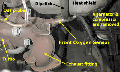
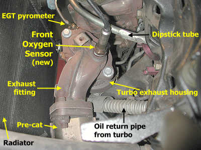
Before installation, inspect the oxygen sensors to be sure they are the correct ones. Even though the factory replacement oxygen sensors have anit-sieze lubricant on the threads, I added a little more just to be sure there was enough. Carefully insert the thimble of the sensor into the opening in the exhaust fitting. By hand only, thread the sensor into the opening until the gasket ring on the sensor threads contacts the exhaust fitting. Continue tightening the sensor with the special oxygen sensor socket and a ratchet. Finish tightening the sensor with a torque wrench to 33 ft-lbs (45 Nm). The picture below was taken through the wheel well with the alternator and AC compressor removed.
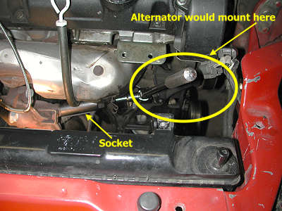
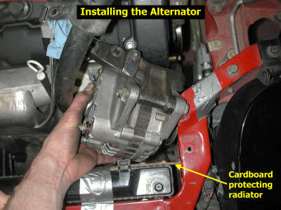
Installation is basically the removal procedures performed in reverse order. Protect the radiator fins with some cardboard. Tape the condensor fan electrical connectors out of the way. The picture below shows the correct orientation to fit the alternator through the space available.
If you are re-using the drive belt, be sure to install it in the same orientation as it had before removal (same side facing the wheel well). Insert the belt from above. Turn it "sideways" to fit it in between the alternator pulley and the AC pipe. Correctly tension the drive belt using its tensioner pulley. Before installing the plastic covers and wheel, temporarily install the IC pipes and battery negative cable and start the engine to check the belt operation. If the belt squeals it is either misaligned or too loose. I found that my old belt squealed when installed "backwards" from how it was removed. It did not squeal when installed in the same orientation. If you have messed with both drive belts, spray a little water on one belt at a time to see which is squealing. A misalligned belt will stop squealing for a very short time after water is sprayed on it, but the squealing quickly comes back louder than before. If the belt is loose, the squealing will immediately get louder. Also note that there is just a little play in how the alternator bolts in. If misalignment is a problem, loosen all four bracket mounting bolts (this may require again removing an IC pipe), reposition the alternator, and tighten the bolts to see if this helps. Do not tighten the belt too much because this can lead to shaft bearing failure over time.
Here are some links concerning drive belt adjustment.
http://www.gates.com/brochure.cfm?brochure=1026
http://www.ridgeautoparts.com/tips/the_charging_system1_2.htm
http://www.utfleets.com/library/features/accessory_drive_belts.htm
After you are satisfied the drive belt is installed correctly, disconnect the battery negative cable and re-install the other parts. Tips for mounting the wheel are on my web page 2-tirerotation.htm. The last thing to do is re-connect the negative battery cable.
Page last updated June 6, 2005.