Sony CDX-M800 Head Unit Installation
in the Mitsubishi 3000GT/Dodge Stealth

by Jeff Lucius

Introduction

These tips show how I installed the Sony Xplod CDX-M800 CD receiver automotive audio head unit in the dash of my 1992 Dodge Stealth Twin Turbo. I had two motivations for replacing the factory two-component receiver and CD player: to improve the audio system and to make available one DIN opening for my A'PEXi S-AFCII airflow signal controller. I selected the CDX-M800 because I did not want or need an MP3 player (though the CDX-M800 can play MP3 files if a Sony CD Changer is added) and I do not particularly like the looks of most receivers. I prefer a plain, non-gaudy appearance, and the CDX-M800 provides this when the faceplate is closed. The CDX-M800 also has RCA connections for line-level output in case I add external amplifiers. I had considered the CDX-M850MP, which plays MP3-encoded discs and has a higher line-level output, for only about $50 more. However, the face is outlined in silver and I wanted only black showing when the face is closed.

I purchased this head unit from SoundDomain.com for $239.95 (Sony ERSP is $329.95). In November 2003, the CDX-M800 was available from Discount Jungle for $198.50. Descriptions of the specifications and features of the CDX-M800 can be found at the Sony CDX-M800 web page, at SoundDomain.com's CDX-M800 web page, and at Crutchfield's CDX-M800 web page. I found two excellent reviews online for the CDX-M800: Ken C. Pohlmann's Face the Music and Mike Frost's Car Audio Magazine's Sony CDX-M800 Test Report.

Sony CDX-M800 CD receiver automotive audio head unit

The key features of the Sony CDX-M800 include the following.

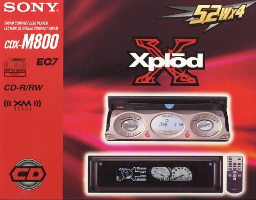
Selected Sony CDX-M800 Specifications
CD Section (from Car Audio Magazine)
Frequency Response +0/-0.5dB 20Hz-20kHz
Distortion (THD+N, 1kHz) 0.05%
Stereo Separation 72dB
Signal-to-Noise ratio 78dB (Sony says 90dB)
FM Tuner Section (from Sony's specs)
Frequency Response 30Hz-15kHz
Distortion (THD, 1kHz) 0.5%
Stereo Separation (@ 1kHz) 35dB
Signal-to-Noise ratio 67dB
FM Usable Sensitivity 9dBf
Selectivity (@ 400kHz) 75dB
Power Amp Section (from Car Audio Magazine)
Maximum Continuous Power 24.6W x 4 (4 ohms, 5% THD+N)
Distortion (THD+N, 1kHz) 0.075% (4 ohms, 15.5W)
Preamp Section (from Car Audio Magazine)
Output Level 2.25Vrms (0dB CD)
Bass Control +/-10dB @ 62Hz (Peaking)
Treble Control +/-10dB @ 16kHz (Peaking)
Equalizer +/-10dB @ 62Hz, 157Hz, 396Hz, 1kHz
2.5kHz, 6.3kHz, 16kHz (Peaking)

Installation

I was quite surprised at how easy it is to install the CDX-M800. With the Scosche wiring harness connectors, part MC01 if there are 2-connectors (used up to and including 1993 models) or MI02 if there is 1 connector (used in 1994 and later models), it is a simple matter of splicing the wires to the head unit wires, fastening the head unit to the factory brackets, and plugging everything in. The Scosche stereo connectors are available at SoundDomain.com and many other stores. Because I was not ready to install the A'PEXi S-AFCII, I purchased and installed the factory stereo accessory box (MB877180), pictured below. It is formed from ABS plastic. I purchased it for $11.36 from Tallahassee Mitsubishi by phone (1-888-825-5648) with the "club" discount (list price is $15.15). This box is so handy for storing a few CD's and the CDX-M800 remote that now I am thinking I should install the S-AFCII somewhere else. The pictures below show the box in the correct orientation for mounting.

Stereo accessory box (MB877180)

The trim piece that goes around the factory radio is called the "Radio Panel". The model with one large opening is part MB604650. The model with two DIN openings, like shown on this web page, is part MB604652. Both are available only in black and are applicable for all models and years.

The recommended tools include: a trim removal tool (or something similar), a #2 Phillips screwdriver, a wire cutter and stripper tool, a soldering iron (the one I used is rated at 30 watts with a 700ºF tip temperature), rosin-core solder, 1/8" heat shrink tubing (and some 3/16" too - see sample products below and for example PartsExpress, 9th Tee Enterprises, or Circuit Specialists, Inc.), electrical tape, cable ties, one male bullet connector (22-16 AWG), a permanent marker, a multimeter (a digital volt-ohm meter works great), paper clips if the probes on the multimeter cannot be inserted into the wiring connectors, and a "helping hands" portable benchtop vise with small alligator clips (available with a magnifying lens for less than $5 at All Electronics Corp. or Circuit Specialists, Inc. along with soldering supplies). Please read all of these instructions before performing this procedure.

Heat shrinkable tubing

1. Remove factory receiver and CD player. As a precaution, I first disconnect the negative cable from the battery. Using a trim tool, or similar device, remove the radio panel trim. It snaps in at the top corners and along the bottom edge about an inch or so from the corners. Remove the 4 screws and slide the radio out of the dash. Remove the harness connectors by pressing down on the release lever and pulling on the connector. The antenna cable just slides out of its connector.

Removing factory radio    Back of factory units removed

2. Splice the wires. Identify the wires on the new head unit connector and the Scosche connectors. The wires on the Scosche connectors have labels on the insulation, such as "right front positive" or "illumination". The Sony installation manual identifies the wires by function and color. The Sony light blue wire for "ATT" is used to attentuate (or mute) the sound if attached to the interface cable of a car telephone. The Sony blue/white striped wire for "AMP REM" is used to "turn on" the power relay inside a separate amplifier. Only the "ATT", "AMP REM", and ground wires are not attached to the factory harness. In the pictures below you can see that I took the extra precaution of labeling short pieces of 1/8" shrink tubing with a fine-tip permanent marker and sliding these onto the respective wires on the Sony connector. This will help to avoid confusion while you are splicing wires or for a future owner of this equipment.

3000GT/Stealth stereo connectors

The factory dash and door speakers are wired in parallel as the "front speakers". If you are using the factory 4-ohm door speakers and the 8-ohm dash speakers then there is a total 2-2/3 ohms on the front speaker wire (1/[2/8 + 1/8] = 1/[3/8] = 8/3 = 2.666667). If you have 4-ohm aftermarket speakers in the dash then there is a total 2 ohms on the front speaker wire (1/[1/4 + 1/4] = 1/[1/2] = 2/1 = 2).

There is a positive and negative wire for each speaker (left front, right front, left rear, right rear). For 1991-1993 models (and apparently for all models according to the service manuals), there is no ground wire in the factory harness. The receiver is grounded through its frame through the bracket it is fastened to and then through the metal frame of the floor console to the car's frame/body and battery ground.

Splicing wires from harnesses

CDX-M800 connections

Click on the "3" Sony connections diagram above to open a new web page with a 1159 x 800 pixel version of the image (207 KB).

To splice the wires I basically just twist the wires together, tin them lightly, and insulate the exposed copper with shrink tube (a person could use electrical tape instead). An alternative method would be to use insulated crimp terminals of some sort, such as butt splice or bullet connectors. I would avoid the use of quick splice connectors (the "guillotine" connector) or twist-on wire caps (these might be OK if sized correctly).

If you are not familiar with soldering, wire stripping, and heating shrinkable tubing, then I recommend practicing with some spare wire. Once you are comfortable with the techniques then work with the connector wires. On the Sony connector, some of the wires were longer than others. Because all the wires on the Scosche connectors are the same length, I trimmed these longer wires to the same length as the shorter ones. Strip about 1/2" of the insulation off the end of each wire on the Sony connector that will be spliced. Before splicing the connector wires, slide a 3/4" long piece of 1/8" shrink tubing onto one of the wires. I suggest sliding this tubing onto all the wires that will be spliced before doing any splicing.

Select the two wires that are to be spliced and twist the strands on each wire. Then cross the two wires so that they form a "V" with the insulation of each wire meeting at the base of the "V". Now twist the two wires together. Another technique (see http://www.bcae1.com/installationprimer.htm) would be to form the end of each wire into a "fish hook" shape and then twist each wire back on itself after hooking the two ends together. Use the helping hands to hold the wires while you lightly tin (melt solder into) the exposed copper of the twisted wires. Remove the iron and let the wires cool for 15 seconds or so; the surface of the solder will turn from shiny to dull when it cools. Bend the tinned copper wires over to lay against the insulation. Slide the shrink tubing down across the tinned wires so that it overlaps onto the insulation on each side. You may need to "crush" the soldered wires a little to make the shrink tubing fit.

Splicing wires from harnesses

After you have spliced and tinned all the wires, then you want to use heat to shrink the tubing. Turn your soldering iron off, or unplug it. You will want to clean this tip or use a tip dedicated for heating the plastic shrink tube. While the iron is cooling you should check your work for electrical continuity. Set your multimeter to read "ohms". Identify the terminals in each connector that a single (spliced) wire attaches to. Insert the multimeter probes into the connector. You may need to use a straightened paper clip inside the connector and then touch the probe tip to the paper clip. If there is continuity the multimeter should read some small amount of resistance. My digital meter indicated about 0.1 ohm (0.7 ohm minus the 0.6 ohm present when the two probes are touched together). If the multimeter indicates open (0L on a digital meter, which means no electrical continuity) or a high resistance (more than 0.1 or 0.2 ohm after the base value is subtracted) then take a close look at this wire where it attaches to the connectors and where it is spliced.

After performing the continuity checks your iron should be cool enough to remove the tip. Use pliers to unscrew the tip if you are replacing it. Otherwise, clean the solder off the tip with the "sponge" or a fine file. Be sure the tip is on tight and turn the iron back on (or plug it in). To shrink the tubing, quickly glide the iron tip across the tubing. Do not let the tip rest in one spot or you risk melting the tubing. Heat all sides of the tubing. Working from the center, shrink one end first till it seals around the wire insulation. Then shrink and seal the other end of the tubing. You know the tubing has shrunk enough when you cannot slide the tubing. There should be no bare copper exposed. If you do have some exposed wire or managed to melt through the tubing (I did for one splice), wrap a little bit of electrical tape around the splice. Be sure to turn your soldering iron off (or unplug it) when finished.

The blue "ANT REM" wire (it turns on the power antenna motor when the FM or AM source is selected) on the CDX-M800 connector has an insulated female bullet connector on the end. Rather than cut this connector off, I crimped a male bullet connector to the blue wire of the Scosche connector. The CDX-M800 ground wire has a spade connector on its end. The next section describes where to attach this wire.

Completed harness adapter

back of Sony CDX-M800

3. Attach factory brackets to the CDX-M800 and accessory box. Attachment configurations must be fairly standard. The CDX-M800 has five holes in each side of the case to be used to mount the unit. I have identified in the picture below the two holes that are used with our factory brackets. I used a permanent market to draw small arrows on the case to indicate these two holes (look just to the left of each blue arrow head). Use the Sony-supplied screws to attach the CDX-M800 to the factory brackets. I chose to mount the unit in the upper DIN opening. The brackets have "L" and "R" stamped into them to identify the left and right pieces, respectively. Attach the ground wire to one of the mounting screws. Use four screws from the factory components to attach the accessory box. The box is oriented so that the part number stamped into it is "right side up". Look carefully at the rear-view picture below. Just line up the molded-in openings of the box with the bracket holes and carefully start and rotate the screws into the openings, which are not threaded so you will be cutting a thread pattern into the ABS plastic. Tighten all the screws. I used a couple of cable ties to bundle the wires together.

CDX-M800 mountingholes

CDX-M800 with brackets attached, front

CDX-M800 with brackets attached, back

4. Install the CDX-M800 in the dash. Practice attaching and then removing the CDX-M800 trim before installing the assembly in the dash. The very little square tabs on the back of the Sony trim are on the bottom edge. Note the posts on the floor console frame that the brackets will slide onto. Attach the stereo connectors and the antenna cable. Slide the assembly into the opening, being sure the curved part of the brackets slides onto the posts. Attach the four screws. Attach the radio panel trim. I had to angle the top in to get it started above the CDX-M800. Snap it into place. Snap the CDX-M800 trim piece into place. Re-attach the negative battery cable if you removed it.

That's it! You are now ready to learn and enjoy your new receiver and CD player. In the pictures below, the black face of the CDX-M800 shows the underlying fluorescent display because of the flash photography. In normal light, when the ignition switch is off, the display is black with just a hint of the underlying display visible. When the ignition switch is on and the unit is off, the face is black except for the two small blue-lit buttons in the upper corners, with the option of displaying the time or Sony "demo" info on the face.

Opening in the dash

CDX-M800 attached to factory harness

CDX-M800 installed, no trim

CDX-M800 installed, face closed

CDX-M800 installed, face open


Back Home Forward

Except for the small gif and jpg images, the content, images, photographs, text, and multimedia displayed are Copyright © 2000-2007 by Jeff Lucius and K2 Software. All rights reserved. No part, section, image, photo, article, or whole of this site may be reposted or redisplayed without permission of the author.
Page last updated January 21, 2007.