Installing a Thomas Knight Roots
Style Supercharging System on a Mitsubishi 3000GT
By
This web page documents my experiences with installing a Thomas Knight Supercharging (SC) system (http://www.boosthead.com/) on a DOHC 1994 Mitsubishi 3000GT non-turbo. The system I purchased consisted of a MP90 Magnuson 4th Generation Eaton Supercharger, lower 6G72 intake manifold, throttle body adapter plate, intake manifold adapter plate, plenum spacer, supercharger adapter plate, fuel management unit (FMU), idler pulley, lower supercharger support brackets, throttle cable mounting bracket, accelerator cable adapter, 6-rib belt, remote brake reservoir, mechanical boost gauge, bolts, washers, hoses (fuel and vacuum), vacuum connectors, hose clamps, etc... Please note that not all items are pictured below but will be identified in the body of this document. I’m sure that I have overlooked a few minor steps but nothing of significance. Please read this entire document before starting the installation.
I plan to update this web page after I add a supercharger bypass valve when I perform the 60K maintenance. I also plan to install 360 cc injectors with resistors. So check back!
This web page is also available as MS Word and Adobe PDF documents.
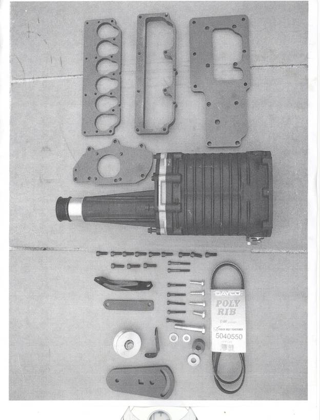
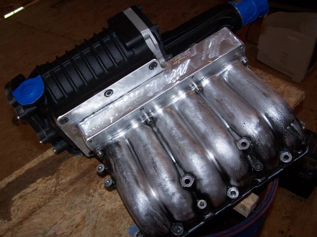
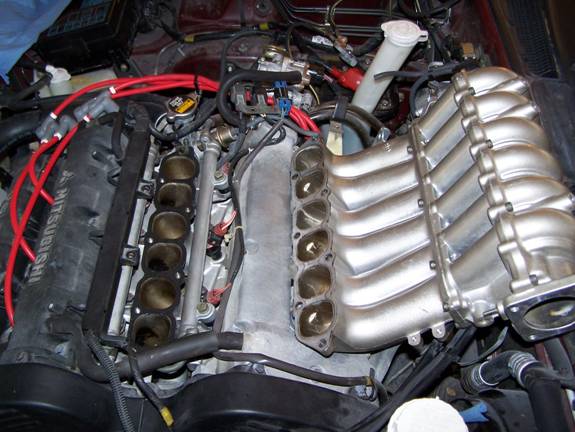
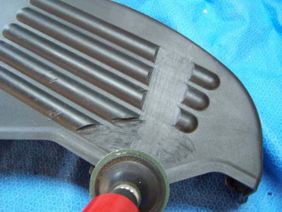
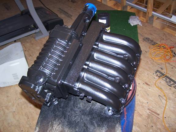
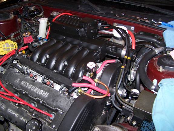
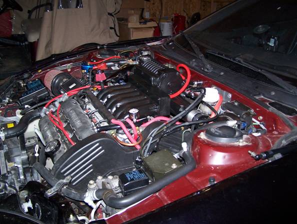
Mr. Knight assembled the unit as pictured below but I believe he did so to insure fit and alignment on his mock motor. My unit is considered his 14th generation which places the SC at nearly the center line of the hood which was done to give the customer a greater variety of hood scoops as the SC requires hood relief (the SC sets approximately ¾ inch above the hood line). Please note that the unit does not look this way as purchased. This was after I did a couple hours worth of grinding, wire brush cleaning, taping, all done in preparation for painting.
Warning:
With this installation you are
going to encounter many small bolts, nuts, pins, clamps etc., which 1) you need
to keep organized and 2) you need to be very careful not to drop anything from
tools to nuts into the abyss. I can’t
begin to tell you how important it is to plug and cover these black holes and
to remember what goes where; of course you have this guide to help those with
dementia. I would also strongly suggest
to not reuse any gaskets as once the Supercharger system is installed you will
be taking the engine from a vacuum oriented system to a pressured system and it
is very important to make sure all mating surfaces are completely sealed.
Don’t be in a rush; take your time; have a camera at the ready; read this guide from end to end before you start the project; give yourself plenty of time. I would guesstimate that this entire project can be accomplished over a weekend at a leisurely pace assuming no painting, little to no fabrication, and you have all your parts and pieces to avoid running back and forth to O’Reilly’s. It really helps to have a friend to give you a hand especially if he or she is mechanically minded. My wife with her small hands proved invaluable in starting bolts in a couple of tricky, no room for fat hands areas and pulling and routing wires and vacuum hoses under the dash in the cockpit.
Oh, make sure you have a first aid
kit handy and for you older guys like me a defibrillator.
Okay lets get
started:
Step 1
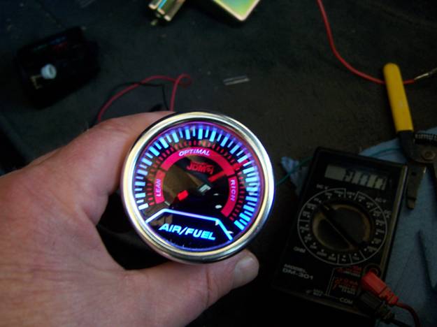
I hooked up a narrowband Air/Fuel ratio gauge to establish an A/F ratio base line as I wanted to insure that I could keep an eye on any possible lean operations in the early part of the project. Because all gauges read differently I wanted to understand how my A/F ratio gauge would be reported in my application. As seen in the picture, my gauge reported just near “rich” on the dial. What this equated to on the A/F scale I don’t know but I had my baseline. The needle will dance from left to right with maximum right swings indicating A/F ratio. Narrowband gauges are an off/on reporter. If I had this to do again I would have installed a wideband unit from the get go because eventually most folks find themselves working on the fuel delivery system.
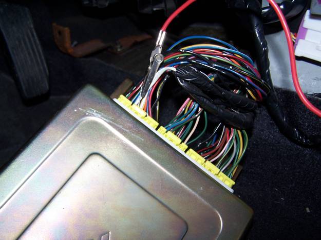
For my application I had to tap into pin #56 on the ECU for the O2 signal, then added a 12-volt switch source and ground. I left the gauge installation and reinstallation of the ECU for the last steps. You may want to check your ECU pin placements for the pin number that supports the O2 signal because there are changes in some years as well as the ECU themselves. The links below provide some basic ECU information.
http://stealth316.com/2-ecmremoval.htm
http://stealth316.com/2-ecu-terminals.htm
Step 2
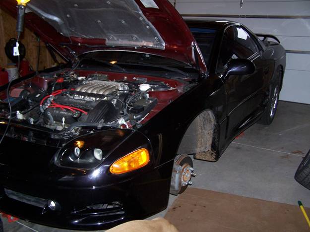
Raise the car on stands to about 12” off the floor. This is really a must for all you old guys as this work will raise hell on your back due to all the stooping. You will need to pull the driver side front wheel to access the accessory and power steering belts which will ultimately drive the SC. You will also be removing the power steering idler pulley and replace it with the SC idler bracket and pulley. The link below has some information about raising and supporting your Stealth or 3000GT.
http://stealth316.com/2-raisecar.htm
Step 3
Remove Hood. Use a felt marker to mark where hinges were positioned for a no-alignment reinstall. You will have to disconnect the window washer hoses and engine compartment light, which I eventually eliminated. Position a bright light above the engine compartment and dig in!
Step 4
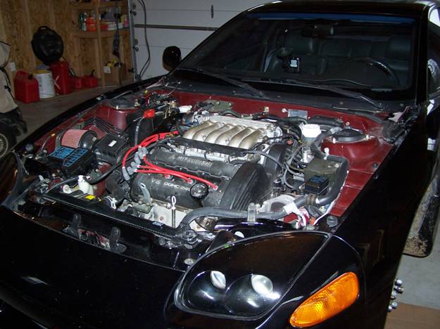
Take a real close look at the engine and all it’s hook ups, you may want to take pictures in case your memory is bad like mine.
Note: I long ago removed my factory air intake box and filter assembly in favor of a more performance-oriented setup.
Step 5
Remove air filter, MAS, air intake tube, and battery. Make sure to protect electrical connections to avoid inadvertent damage. Most if not all of the electrical connections are unique so you don’t have to worry about reconnecting things incorrectly.
Step 6
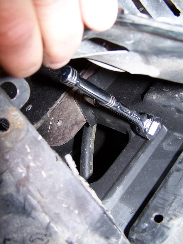
Remove the lower driver’s-side engine splashguard (also called the engine room side cover). There are both rivets and bolts that hold this unit on. This will give you access to the accessory, power steering (PS) belts and PS idler pulley, all of which must be removed.
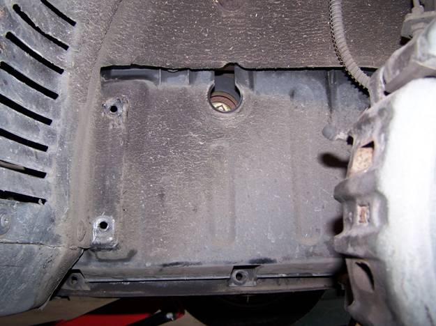
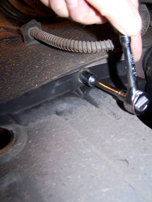
These bolts are in back of the front wheel well. You will have to unbolt and pop a few rivets to get at these bolts. Don’t worry about saving rivets as any auto store has replacements and most likely you will break or distort the rivet to the degree they will probably not hold well if they are reused.
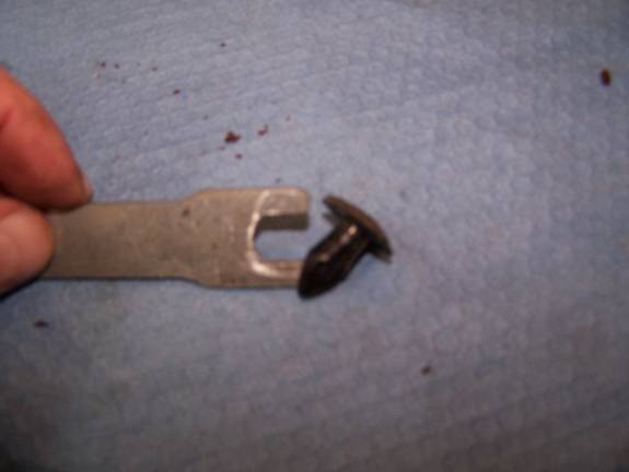
My rivet removal tool.
Step 7
Pull accessory and PS belts plus PS idler pulley and bracket. (Sorry, I can’t find the pictures!)
The accessory drive has an idler pulley that you unloosen by backing off the tensioning adjustment bolt. For me this was a bear to get the belt off and on but just keep trying and work slowly.
Note: I left the splashguard off until I had all the belts adjusted properly and the SC belt will need to be adjusted 3x or more, as I did not want to over tighten. I adjusted the accessory belt 2x and could probably use another adjustment because when temps get real high and running the AC I will hear an occasional squeal. Here is a link with some more information.
http://stealth316.com/2-ps-drivebelt.htm
Step 8
Disconnect all electrical connections to the throttle body (TB) and remove the 10-mm bolts holding the control-wiring mount (the bracket just right of the TB that contains a blue electrical connector). Also unplug the vacuum hose attached to the TB.
Step 9
Disconnect the two connectors that operate the Variable Induction Control Servo. They are kept in place by wire pins so be careful removing them or the pins may fly off into the abyss. The servo will not be reconnected for the SC install. I suggest that you do not cut the wires but merely wrap with electrical tape and stow it out of sight.
Step 10
Remove the vacuum hose from the Brake Booster Cylinder. I replaced this vacuum line but I suggest that you keep all the parts, as you never know when you might use them. Now would be a good time to unhook the throttle cable and unbolt the mount from the upper intake plenum. You may also wish to unbolt the bracket from the firewall that secures the cables for the cruise control.
Step 11
Remove the four 10-mm bolts that secure the throttle body (TB). The bracket that holds the vacuum hose in place will not be reinstalled. In addition, the vacuum port on which the vacuum hose is attached to the TB will be plugged. I would advise that all gaskets be replaced as vacuum and boost leaks can greatly affect the engine’s performance.
Disconnect the two coolant hoses attached to the TB. Remember which goes where! These hoses will need to be replaced due to the need for longer length. Hey, the hoses are probably old and replacement will add a little insurance against leaks.
Step 12
Unbolt the cruise control unit and set it off to the side. Do not remove, as it is not necessary. This step will merely provide you with a little more working room. Although unnecessary, you may want to also remove the mounting brackets for the AC line as this will provide additional room, especially when working with the brake reservoir.
Step 13
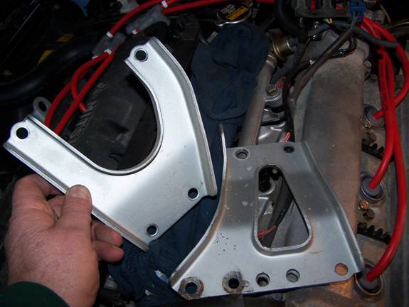
Okay, now we are getting to the real meat. You should be ready to pull the intake manifold off. Two things to do here, first there are seven bolts and nuts securing the plenum assemble to the lower intake manifold. I would advise that you loosen all the bolts and nuts and remove all but the center three. Next, there are two rear manifold supports; remove the bolts holding the manifold to the support brackets. Once these bolts are removed, remove the remaining three and lift off the manifold.
Now that you have plenty of room, remove the bolts securing the rear manifold supports, as you will not need them for the SC installation. I believe you will find one of the support bolts is used to secure the power steering and will need to be replaced, however, you may wish to use a number of washers to fill the margin left by the support bracket just to avoid the possibility of breaking the PS mounting flange.
Note: Be sure to not forget to reinstall the ground wire when putting things back together!
 .
.
Step 14
Install the fuel management unit (FMU) on the passenger’s side shock tower. Drill 2 holes and mount. You want to keep this unit as horizontal and level as possible. Depending on your air intake system, it might dictate another location, however, I found this the most ideal placement.
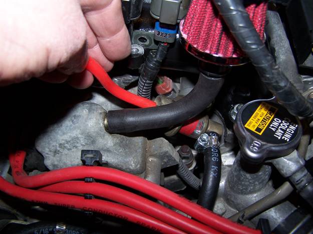
Remove the fuel hose from the OEM fuel pressure regulator (FPR) and then run a fuel hose from the FPR to the input of the FMU. From the FMU run a fuel hose back to the hose that was connected to the FPR. You’re making a new path (for the fuel return flow to the fuel tank) from the FPR through the FMU and back to the return hose to the tank. Because the FPR fuel hose was not long enough to reach the FMU I had to add about 12” of fuel hose. Be sure to use a good barbed brass connector with a clamp, as pressures can be high and you’re dealing with fuel so you don’t want any leaks or ruptures. A vacuum source will be run to the FMU at a later point. My FMU has an 8 to 1 ratio, or, for every pound of boost (1 psi) it will increase (by restriction) the fuel pressure by 8 psi. I’m running 7 pounds of boost, therefore my fuel pressure will be increased by 56 psi. My fuel pump is set for 100 psi so I’ll be maxed out.
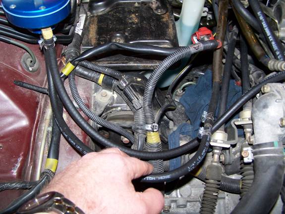
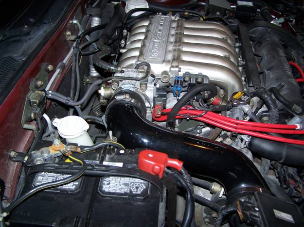
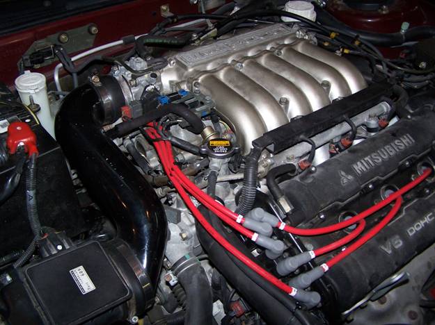
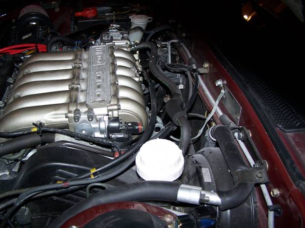
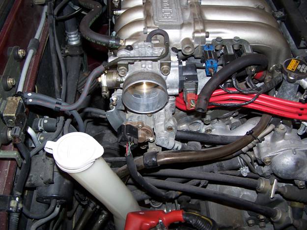
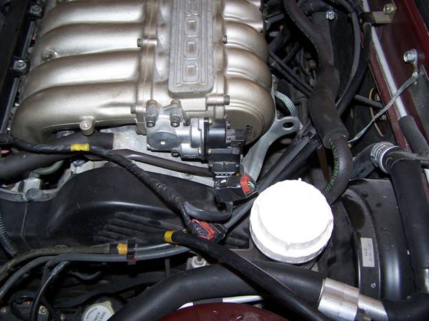
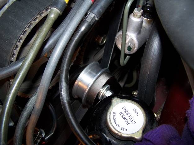
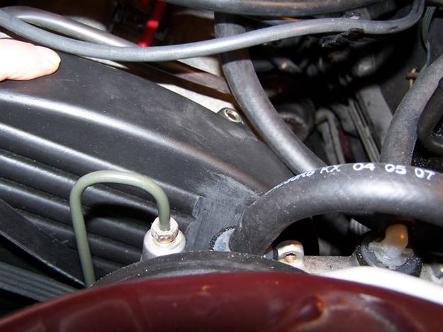
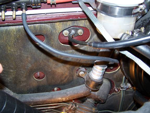
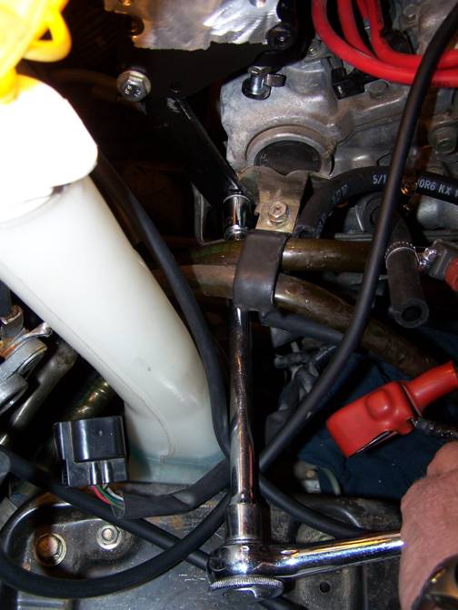
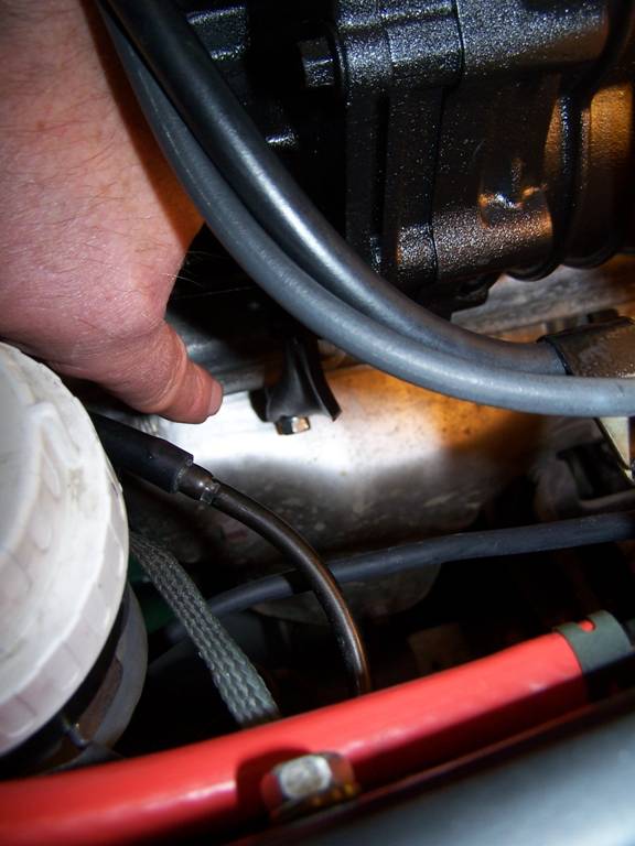
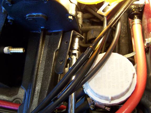
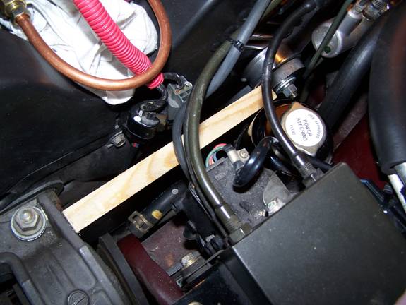
Below is a picture of the fuel pressure regulator (just to the left of the coolant refill cap). The red vacuum hose I’m holding is attached to the top of FPR . The black hose secured by the hose band goes to the FMU input. Fuel now flows from the rear fuel rail through the FPR to the FMU (black hose) and to the original hose that returns fuel to the tank. Fuel pressure is controlled by causing a restriction in the fuel return line from the rear fuel rail.
Note: What looks like a small red air filter is my crankcase vent. Normally this hose would be connected to the air intake tube, but by doing so would draw engine oil vapor into the supercharger, which I wanted to avoid. To vent to the atmosphere is perfectly acceptable.
Step 15
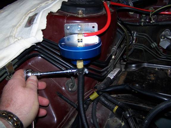
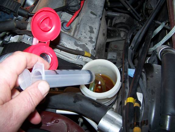
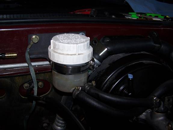
In order to provide sufficient clearance for the SC drive pulley and belt the master cylinder brake reservoir will have to be relocated. Fortunately, the Mitsubishi Eclipse employs a remote reservoir and that is what is supplied with Mr. Knight’s kit. First you have to remove as much brake fluid as possible. I did that with a syringe. Once you have removed all the fluid you can, there is a small screw that secures the reservoir to the cylinder housing. Remove this screw and slowly rock the reservoir from side to side until the reservoir detaches. It is a booger but it will come off. Oh, there are two wires that connect to contacts that signal low fluid level. You will need to extend these wires to accommodate for a new reservoir location. I cut my wires about midway to allow for easy splicing to either side (reservoir or connector).
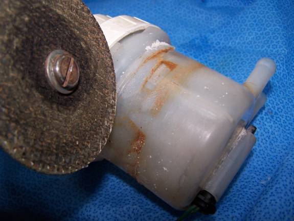
To insure a firm attachment of the mounting bracket, I needed to grind off various tabs from the remote reservoir.
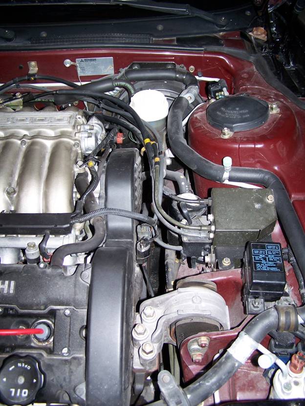
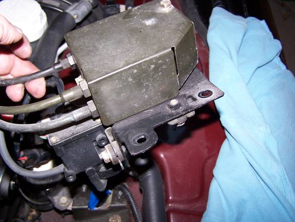
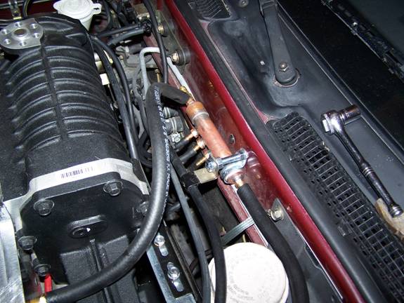
Although the next picture is somewhat dark, it gives you an idea of how and where the reservoir was mounted. Note, to insure that the reservoir would not vibrate loose from the 4” hose clamp, I cut a small rubber strip from an old inner tube and wrapped it around the reservoir body and then placed the clamp around the rubber.
For my application I placed the remote reservoir right along side the brake vacuum canister. Be sure to mount it as low as possible, as I discovered later this would cause a minor hood closing problem. Although difficult to see, the remote reservoir kit comes with 90- and 180-degree nipples to be placed in the master cylinder fluid orifices. This is how you are able to connect the reservoir to the cylinder. These nipples go in extremely hard but they will go in. I would not advise using a hammer, just plane old hand pressure and twisting will seat them. Do not run brake hoses at this time, as it is best to have the SC and belt on so you know exactly how to position the hoses. I didn’t and I immediately wore through a fluid hose on start up.
Note the ground strap.
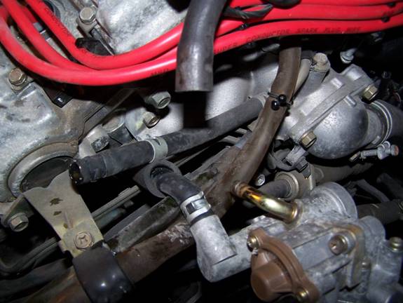
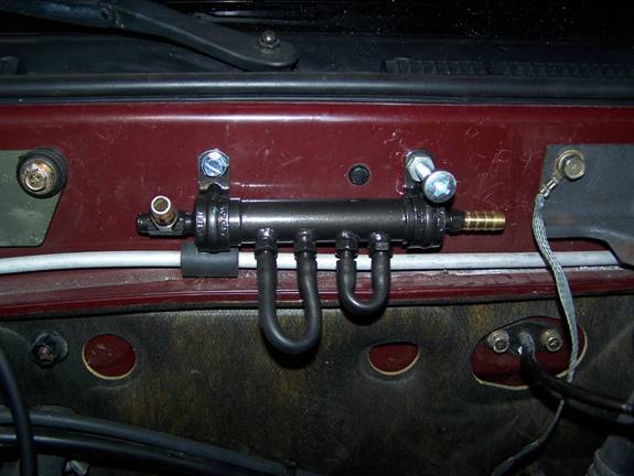
Below is a picture of the hose connections to the brake cylinder. The white 90-degree nipple is nearest the vacuum canister.
Step 16
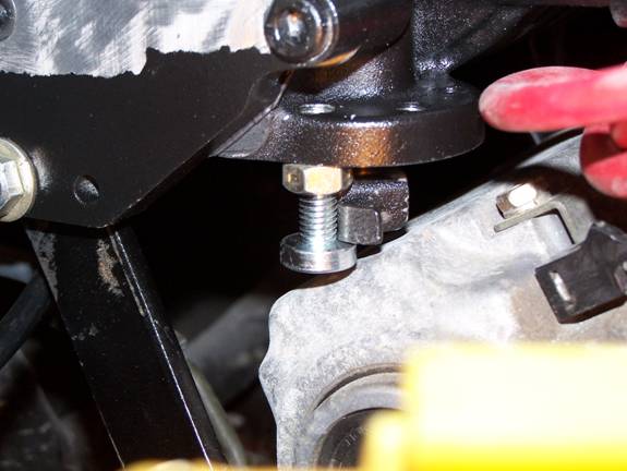
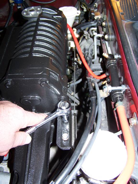
In this step the SC idler pulley and arm need to be installed. Once you secure the pulley to the arm make sure it is 1) SECURE and 2) SPINS FREELY. Now for the fun. This area is tight, but all the bolts have room to be started and threaded on. Just take your time, play soft soothing music and turn bolts a 1/8 a turn at a time.
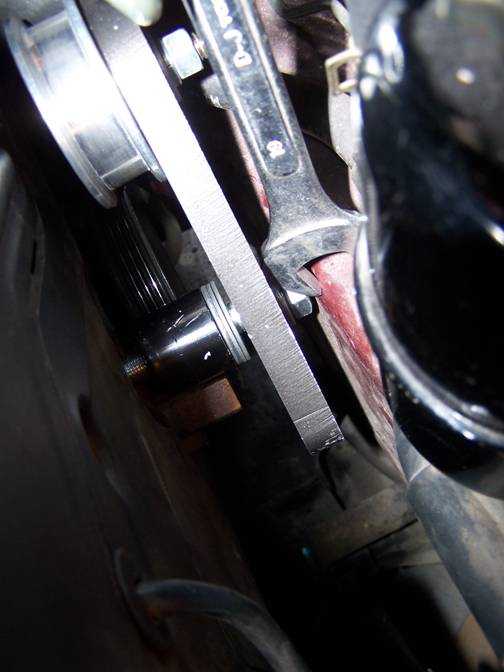
Big tip here which will save you hours of cursing; before you draw the bolts down “snug” be sure to thread the forward side of the SC belt between the SC pulley and pivot bolt. If you don’t you will be back under the car loosing these bolts until you have the clearance to pass the SC belt through the area and then get to turn them back to snug again. I’m so stupid I think I did this 3X before I got it right! I hope this picture tells the story.
Step 17
Wasn’t
step 16 fun! When I did my install I
first did a mockup because I was not sure that whatever decisions I made now
would be the correct decisions once the SC was on. Case in point was determining the exact
location of where to trim the protrusions from the rear timing belt cover. For some installs I saw, guys would totally
grind off all the fins on the covers which looked like hell. I wanted to avoid those kinds of pit
falls. I strongly advise you to do a
mockup because this write-up cannot guarantee that all models of the 3000GT or
Stealth DOHC are the same under the hood
due to years, accessories, and/or manufacturing changes. I do believe that what I have done will completely
work for 94 and 95’s, but there can be subtle nuances that can make a
difference between a professional install and a hack job. I’m not a wrencher, as such, but I knew if I
took my time I could do a professional looking job.
By doing a mock up you would see this (below) with a taut belt. This belt will stretch so you have to allow for some 3/8 inch rearward movement.

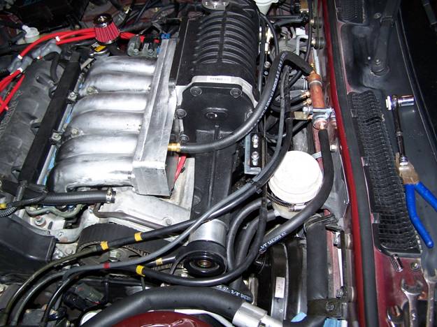
Then when it is on, your result should be as pictured below. Note: another view of those brake hose connections on the master brake cylinder.
Step 18
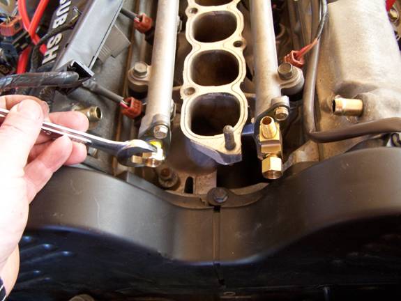
This step I would consider optional as it involves the installation of a mechanical fuel pressure gauge which I mounted between the two fuel rails. I did this because I wanted to visually check the fuel pressure but did not want to add another gauge in the cockpit. Pix below is of the finished installation.
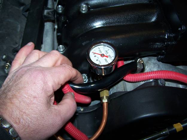
What I did was pull the OEM fuel rail connector out and sawed off the steel pipe where it connected at the flange. Then I merely tapped the flanges for a 1/8 NPT fittings.
I then screwed a ¼” brass compression adapter into the front fuel rail and installed a ¼” Tee using a short nipple to connect the Tee to the rear fuel rail and then screwed a ¼” compression adapter to provide the connection to join the two fuel rails together. To connect the fuel pressure gauge to the Tee I used a 1-1/2 inch long ¼” nipple screwed to the Tee then a ¼” coupling to provide for a female connection for the fuel pressure gauge.
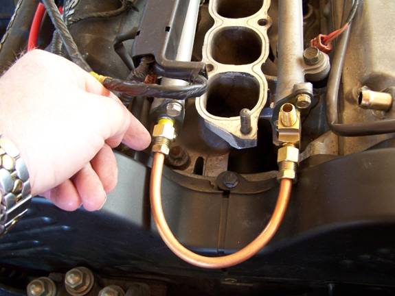
I then connected the two fuel
rails together with a 5/16” soft copper pipe bending it gently to form a
“U”. It is best to do this fabrication
work with both timing belt covers in place to avoid any clearance issues.
Step 19
Providing for a vacuum source. Because I was having so much fun inventing
and fab’n my fuel rail crossover I decided to fab my own vacuum manifold. Now once again I don’t believe it is
necessary to build or purchase a manifold but I did not like the idea of teeing
off of a bunch of different sources to get my vacuums as I was concerned that
sources could vary, tees can leak, and volumes could be an issue. I’ve seen on Ebay where you can purchase a
vacuum manifold for less than $40 (as of 2010), which would provide for up to 6
ports. Well I had a piece of ¾” copper
pipe and a couple of copper caps, a torch, and solder. So I purchased one 3/8” barbed hose connector
with a ¼” NPT end, one 3/8” tee barbed,
and four 3/16” barbed hose connectors with a ¼” NPT ends.
I drilled holes in each end to allow for the larger barbed
connectors and 4 smaller holes in the pipe to hold the smaller connectors and
soldered them in. SIMPLE. Oh, the larger Tee barbed connector I ground
off one of the
With this unit I guaranteed myself one single source with sufficient volume to handle all my vacuum needs. BTW, vacuum needs are as follows. Source: from adapter plenum plate. Outputs: brakes, FMU, boost gauge, evaporation canister, and fuel regulator.
Step 20
Before you install the SC, and while you have room, it is a great time to run a vacuum hose into the cabin for the boost gauge. I found the grommet located just above and to the right of the steering shaft to be a convenient entry.
Step 21
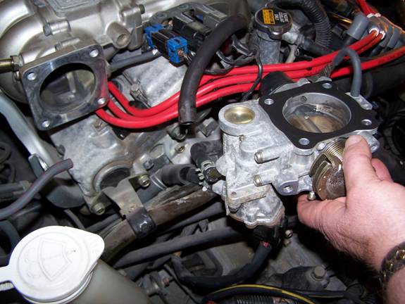
Now it is finally time to prepare the supercharger and throttle body as there are a couple of minor issues.
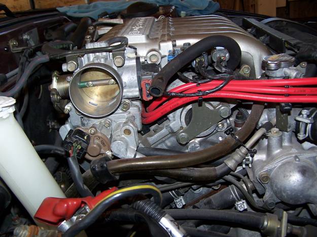
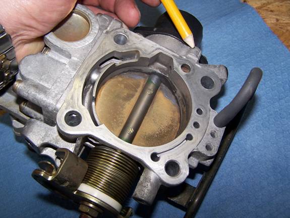
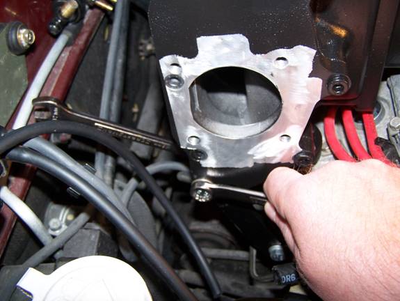
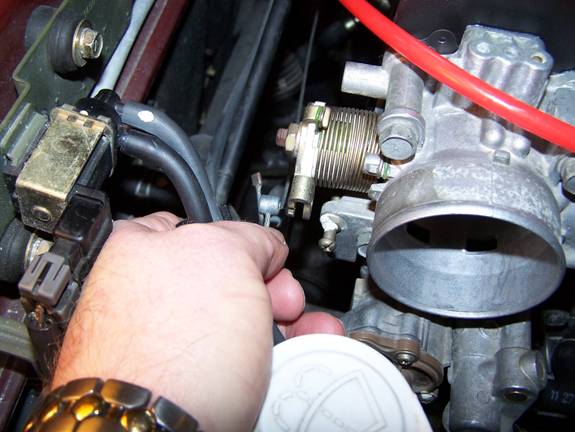
First, you need to grind off the nub at the base of the TB, see picture below.
Second, remove the vacuum hose from the TB, cut off the brass vacuum tube, and plug it. I believe I used a short piece of round plastic and drove it in with a few taps of my hammer. The vacuum support bracket is not used.
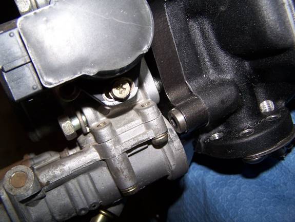
Third, test fit the TB to the TB adapter and check to see if you have this clearance issue (Allen bolt touching the outer edge of the TB). If so, grind on the TB; you can take a little off the bolt head.
Do not install the TB to the SC as you will have trouble getting at the rear SC support bolt.
STEP 22
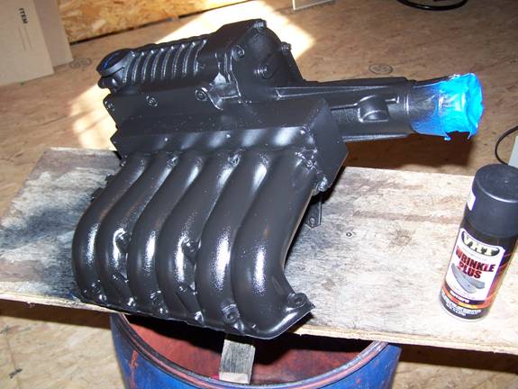
If you’re going to paint or detail
or whatever now is the time. Do not paint
or coat the lower intake manifold surface, TB surfaces, bypass valve shaft area
(both sides) and near SC pulley snout.
Maybe a better way to say it is keep all gasket surfaces and moving
areas clean and free of any coatings and make sure all mating surfaces are smooth.
Step 23
If you are installing a Magnuson unit, Mr. Knight suggests that the SC bypass value is left open just a fuzz (I figured that at about .030 of an inch or about the width of spark plug gap). As you can see, I used a large-headed Phillips bolt with a lock nut to force and hold the bypass valve arm secure.
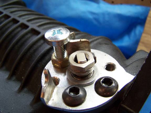
You only have a little clearance (rear valve cover) with this setup. So don’t go using a long or thick headed bolt if you choose this type of setup.
Step 24
Loosely mount both rear SC
supports to the engine block. I can
almost guarantee that these brackets will take a little minor adjustment to fit
easily. Once again, another good reason
for doing a mock up.
Step 25
You are now ready to place the SC intake manifold assembly on to the engine. You may use gasket sealer, but employ with use of a manifold gasket, and only use sealer to “wet” the gasket. With help, lower the assembly onto the lower intake manifold being careful not to disturb the gasket or nick any mating surfaces. Once setting in the lower intake manifold, install all 7 intake manifold bolts and nuts to a snug fit.
Now locate the rear passenger’s
side support and secure it to the SC.
Locate the driver’s side support and secure it to the SC.
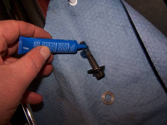
Be sure to use Loctite on all
bolts that hold the SC end plates. BTW,
all SC end plate bolts should be torqued to 10 lbf-ft. Intake manifold bolts may be torqued to 10 lbf-ft.
Step 26
Hook up the accelerator assembly. First, mount the accelerator bracket. I made up a slightly different mount than what was supplied to me as I felt the angle was not steep enough or too steep depending on which bolt you used to mount the accelerator bracket. The mount I made put the accelerator cable more parallel with the SC and made the approach angle more moderate. Don’t get me wrong, the bracket supplied would work but I did not want to install it higher on the SC and, because there is so little room to work and clearance, moving the cable closer to the SC freed up a little more work space.
Next mount the accelerator cable housing
bracket to the mount. Don’t be concerned
with some of the pictures especially when they depict a part painted then not
painted or a part that may look different from a like part shown in an earlier or
later picture. This may be caused by a
photo I began taking during mockup verses finally assembly and/or a part that
may have been subsequently modified from what was depicted in an earlier
photo.
Finally, hook the accelerator extension to the end of the factory cable and place it into the accelerator throttle cam.
Step 27
Now hook the coolant lines up to the throttle body. Because the throttle body is located slightly more to the passenger side that the original position, you will need to run new lines because the old ones will not stretch that far and, besides, there is no reason to take a chance on leaks in this area. You did remember which lines go where didn’t ya?
Well I remembered!
Step 28
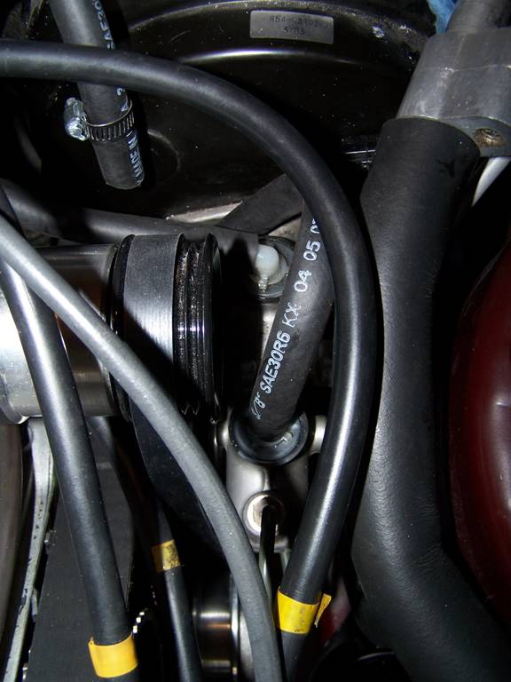
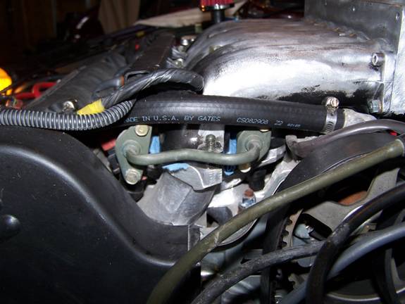
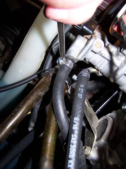
In my setup I was not comfortable with the location and routing of the factory power steering lower hoses so I pulled them off and ran new hoses to provide more clearance for the SC belt. I should point out that the SC belt does not have to be tight, but should be snug. So that it is evident as to where to run the PS hoses and cable tie them out of the way.
Now you need to reinstall the cruise control unit which will require you to remove the SC belt from the SC snout (or at least I did) because I found the best way to run the cables was as shown in the picture below. The accelerator cable to TB was run around the front of the SC pulley. The accelerator cable from the cabin was run under the SC snout and the cruise control cable and vacuum hose was run over the top of the snout. I found that this routing provided the smoothest pathways.
You may secure the AC hose down at this point if you have not already,
In the picture below you can see how that stand-off (right side mounting bolt of the vacuum manifold) aids in securing the cruise control cable. Go ahead and place the SC belt back on the SC Pulley and snug up the belt. Be sure it is seated on the crank pulley and PS pulley. Check to insure that the belt is riding on the center of the idler pulley. If not, you can move the belt to a different rib on the SC pulley as the belt does not have to ride on any particular ribs of the pulley so consider that as a fine adjustment for tracking. Since your on your back, now is as good as time as any to reinstall your accessories belt. It may not be a bad idea to replace with a new belt unless you know the current one is in good shape. I believe that I paid less than $13 for a good Gates Micro V belt.
Step 29
Okay, you now need to run the vacuum hoses. First, get your vacuum source from the SC Plenum adapter, which was tapped, with a 3/8” barbed fitting and run that to your vacuum manifold. Second, run your large vacuum output to the brake vacuum canister. The four small 3/16” outputs service the boost gauge, FMU, fuel regulator, and emissions evaporator.
Step 30
Almost done! I think you are ready to install the air intake tube, Mass Air Sensor (MAS), air filter, and battery. Don’t forget the MAS connector!
Step 31
Okay, this part is a touchy feely thing, as I don’t know how to describe just how tight to make the SC belt. One thing you want to avoid is to over tighten the SC belt from the get go. I couldn’t get my breaker bar into the square hole that Mr. Knight engineered into the idler pulley support so what I did was cut a piece of wood that was long enough to hold the belt tight while I got underneath the car to tighten the idler support bolts. I made the belt tight enough that it was somewhat difficult to make the belt move by pressing on it with my finger. You are going to have to retighten this belt at least 1 or 2 more times to get the squeal out. If the belt squeals it means the belt is slipping. I found that the belt squealed slightly when I first started the engine but knew the belt was going to initially stretch so I drove a few miles before I readjusted. To readjust I cut a few pieces of inner tube and made a couple of folds and placed the rubber folds on the end where the piece of wood contacted the motor mount then retightened the idler. After driving the car for 20 miles or so I would get a light squeal when under full boost and hard acceleration so I repeated the procedure with an additional fold. I have put on over 5k miles and I get a faint squeal at times and I guess I should adjust it again but I would have to jack up the car, pull the wheel and splash guard off, get out the wood stick and rubber strip, adjust, then put it all back together and …. Just writing about it makes me tired I think I’ll wait until it squeals more often or can get a breaker bar to fit into the support hole and do it from the topside, which so far I have been unable to do. Maybe you will come up with a simpler way and tell me how you did it!
Step 32
Don’t forget to reinstall the lower engine splash guard but I would only do it when you feel certain you have both belts properly adjusted. And for heavens sake don’t run the car without the lower splash guard as you will only be asking for problems due to dirt, water, and debris of all kinds. Just leave the splash guard off until you have completed your final belt adjustments.
TIPS:
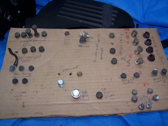
It helps to stay as organized as possible so that you 1) don’t loose anything, 2) help remember where things came from so that you can put them back, and 3) store notes. I devised a way of keeping track of bolts and such going one step higher than the evolutionary coffee can and that is the cardboard organizer.
Special Note: 6-rib Supercharger belt.
If your kit comes with a 6-rib belt you will either have to cut two ribs off the belt or buy a 4 rib belt as this is a 4 rib setup. Cutting 2 ribs off is about as easy as buttering bread. I mounted a blade in my vice and started cutting the belt from the outside inward until I got to the 5th rib’s “V” then slowly pulled the belt against the blade and sliced off 2 ribs. I did this with the ribs facing upwards.
Hood Clearance
Issue
Because the Thomas Knight 14th Generation Supercharger System profile sets higher than the factory hood line you will have to create a relief for the supercharger.
Not to spend a great deal of time on this subject as this is a personal part of the project “Cosmetics”. I’m just going to generally layout how I determined where to position the relief “Cut the hole”.
First, install the hood. Hopefully you took my advice and marked the location of the two hood hinges so the hood will go right back into its original position.
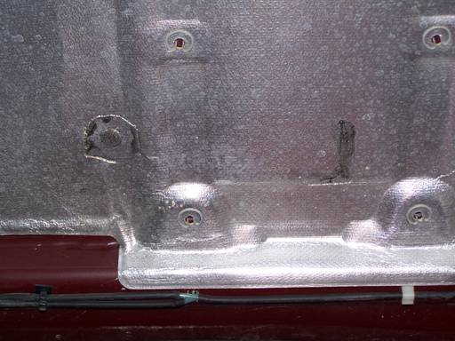
With the hood insulation still in place I painted the highest parts of the SC will a dark moly grease knowing that when I lowered the hood a greasy imprint would be left on the silver insulation. I guess you could just slam the hood down and create impressions that way but I’m sure some would literally slam the hood down which would no doubt create the impressions and as a bonus buckle the hood. Your choice!
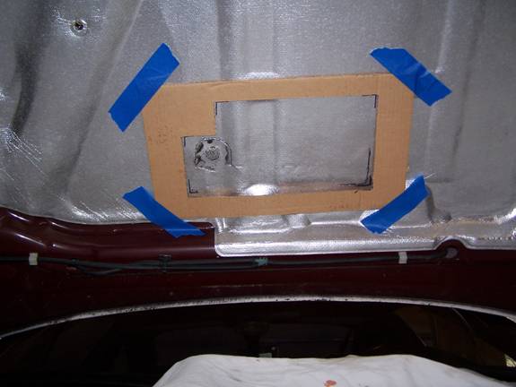
Once I had my reference marks I made a template so that I could drill locater holes through the hood to place the template on the outside and cut with a cutoff wheel.
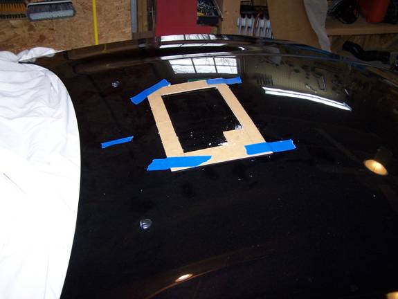
I then took a cut off tool and whacked away. Keep one thing in mind, that when the hood is fully closed the actual location of the final hole will need to be rearward. Be sure to allow for this situation otherwise you will be like me and have to re cut the hole 1x or 2x. Make sure your hood scoop or cover, whatever that choice may be, is sufficiently wide and deep to handle a finish cut hole of approximately 8 x 12 inches. The SC sits within ¾ of an inch from the centerline of the hood. I believe my cut from the rear of the hood was approximately 7 ½ inches.
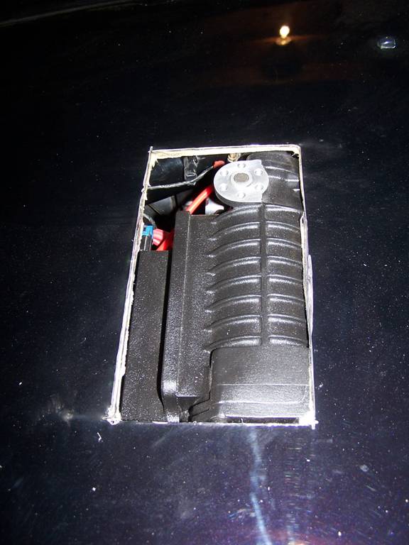
I enlarged the opening in the picture below about 3/8 of an inch larger than what is shown. Also keep in mind that under acceleration the motor will rock rearward and down. Before I put the hood scoop on I took the car out for a drive and under heavy acceleration the SC would rock into the hood which forced me to enlarge the opening especially toward the rear.
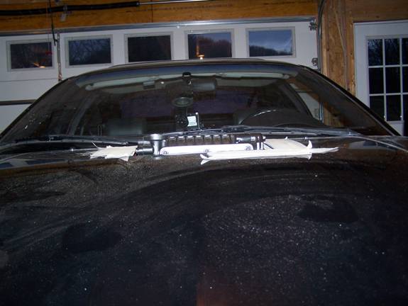
Below is a picture of the hood profile – sorry about the quality but the SC sits approximately ¾ of an inch above the top of the hood.
I chose a 2000 – 2004 Mustang hood scoop to finish off the exterior. I did not make the scoop functional, as I did not want the possibility of water, trash, birds, etc. into the engine compartment.
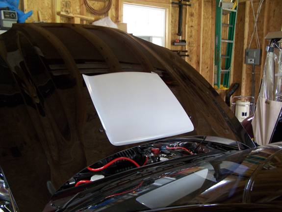
The finish look.

Now go
and burn that old set of tires off your car because you should be making close
to an additional 100hp!!
And at over 400 pounds lighter than a VR4 your power to weight ratio is a little over 10 to 1. A VR4 is about 11.9 to 1.
Authored by