Illustrated Guide to the Mitsubishi 3000GT AWD System

by Jeff Lucius

These pages are still in development. I will add more pictures as I am able to disassemble components or as others send them (pictures or components) to me. If you have comments about this web page or corrections for its contents, please send an email to website at stealth316.com.

Part 1  Acknowledgments
Overview
Part 2  Transaxle Assembly
Transaxle Problems
Part 3  Center Differential/Viscous Coupling Unit
Part 4  Synchronizers
Part 5  Rear Differential, Driveshaft, and Axle Assemblies
Part 6  Propeller Shaft Assembly
Front Driveshaft and Axle Assemblies
Gear Reduction Ratios
Speed in Gears


Propeller Shaft Assembly

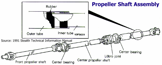
The propeller shaft is a 3-section, 4-joint assembly with two center bearings. The division into three sections increases the natural vibration frequency for bending. Standard cross-style universal joints are used at the #1, #2, and #4 joints of the propeller shaft. Joint #3 is a slidable Lobro-style universal joint with low sliding-friction in the direction of the shaft. The rear propeller shaft section is a vibration-control-type shaft using rubber and an inner tube inserted in the outer tube. All of these features greatly reduce torque fluctuations, vibration, and noise at all speeds.

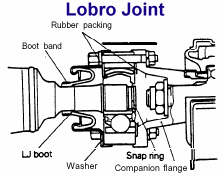
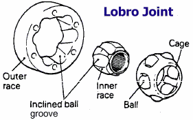
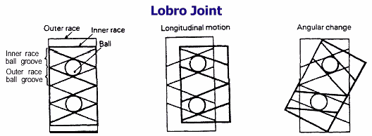
The Lobro joint absorbs longitudinal displacement and angle change and prevents the transmission of vibration. It has excellent constant velocity performance, due to the inclination of the ball grooves of the inner and outer races at the same degree in opposite directions. The balls move the inner and outer race grooves to absorb longitudinal or angular changes. The Lobro joint has a smaller sliding resistance in the axial direction than a spline-type slip joint. It is more suitable for high speed operation than other constant velocity joints due to smaller ball play achieved by crossing the ball grooves of the inner and outer races (leading to smaller rotational variations).

The center bearings are of the dual anti-vibration support type that minimize propeller shaft vibration and noise. The first mount in the center bearing reduces vibration transmission to the floor. The second mount at the bearing-to-floor connection reduces the noise level.

Propeller shaft assembly

Lobro joint details Lobro joint details 2

Lobro joint details 2
Back to top of this page

Front Driveshaft and Axle Assemblies

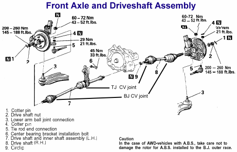
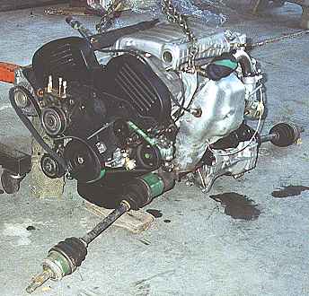
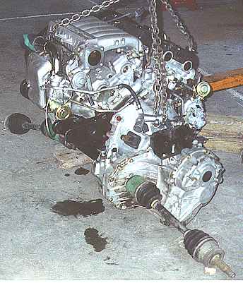
The front driveshafts insert directly into the front differential inside of the transfer case housing. The driveshafts are a two-piece design with a tripod joint (TJ) connecting the two shafts and a Birfield joint (BJ) connecting the outer shaft to the axle. The axle end of the driveshaft is spline-coupled to the wheel hub assembly. The left-side and right-side driveshafts have different lengths.

The TJ-BJ combination maintains rotational velocity completely even when flexed. It can withstand heavy loads and shock, and offers high power-transmission efficiency, low vibration, and low noise. The TJ is used on the differential side of the driveshaft because it slides easily in the axial direction to absorb the change in distance between axle and differential caused by suspension motion. The BJ is used on the wheel side of the shaft because of its compact size and its ability to operate over large deflection angles.

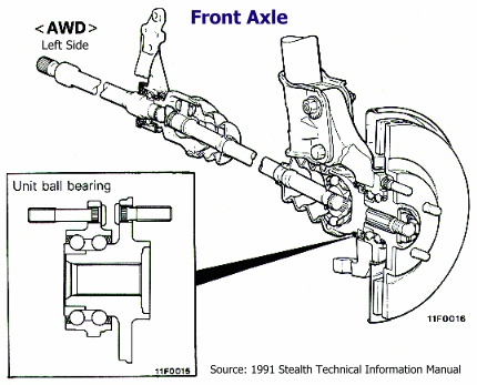
A unit ball bearing consisting of a hub and bearing, as one unit, is used for improved servicing. There is a wheel-speed sensing rotor on the axle shaft on ABS equipped models.

Front axle and driveshaft

Front axle

Front axle and driveshaft 2

Front axle and driveshaft 3
Back to top of this page

Gear Reduction Ratios
3000GT/Stealth AWD Gear Reduction Ratios
1991 - 1993 1994 - 1999
 Primary
 Front differential
 Transfer
 Rear differential
 Speedometer gear 
1.375 (44/32)
2.889 (52/18)
0.815 (22/27)
3.545 (39/11)
27/36
1.222 (44/36)
3.166 (57/18)
0.958
3.307 (43/13)
28/36
Overall 3.972 (2288/576) 3.869
Gear Transaxle Final Transaxle Final
 First
 Second
 Third
 Fourth
 Fifth
 Sixth
3.071 (43/14)
1.739 (40/23)
1.103 (32/29)
0.823 (28/34)
0.659 (31/47)
-
12.200
6.908
4.383
3.271
2.620
-
3.266
1.904
1.241
0.918
0.733
0.589
12.639
7.368
4.803
3.553
2.837
2.279

Calculations
Overall front = primary  x  front diff
Overall rear = primary  x  transfer  x  rear diff
Final gear reduction ratio = overall reduction ratio  x  gear reduction ratio
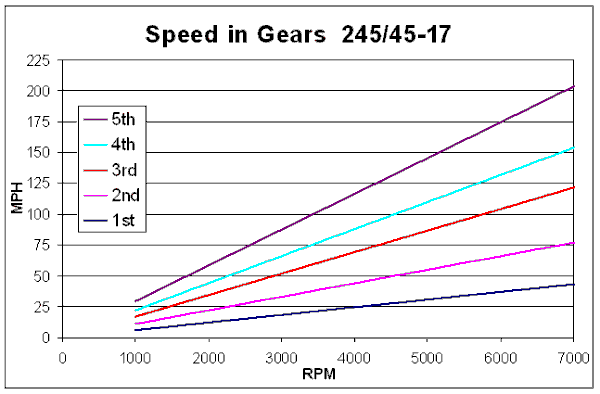
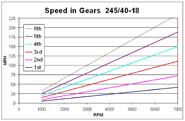
Speed in gear (MPH) = [RPM x tire diameter in inches] / [final gear ratio x 336]

Back to top of this page

Speed in Gears
Speed in gears (5sp)

Back to top of this page
Part 5   Part 5
Back Home Forward
Except for the small gif and jpg images, the content, images, photographs, text, and multimedia displayed are Copyright ©2000-2002 by Jeff Lucius and K2 Software. All rights reserved. No part, section, image, photo, article, or whole of this site may be reposted or redisplayed without permission of the author.
Page last updated March 17, 2002.