Fuel Pressure Regulator Upgrade
for the Mitsubishi 3000GT
and Dodge Stealth DOHC Models

by Jeff Lucius

Introduction

The fuel pressure regulator (FPR) maintains a constant pressure across the fuel injectors. That means the fuel line pressure (at the top or entrance of our injectors) minus the intake manifold pressure (at the bottom or exit of our injectors) is a constant, regardless of engine speed, or manifold vacuum or boost pressure. The FPR connects to the intake plenum using a vacuum hose. When there is vacuum in the plenum, the FPR lowers fuel line pressure 1 psi for every 1 psi of vacuum. When there is positive pressure in the plenum (turbo boost), the FPR increases fuel line pressure 1 psi for every 1 psi of boost. The FPR maintains fuel line pressure by controlling the amount of fuel that returns to the gasoline tank. To increase pressure, the FPR creates a restriction, reducing the amount of fuel that flows through it back to the tank. The factory FPR is not adjustable and has a limit to the maximum amount of fuel that can flow through it. For more information about fuel injectors and fuel injector control in the 3000GT and Stealth, please see my web pages 2-injectortypes.htm and 2-fuelinjection.htm.

Aeromotive A1000-6 (P/N 13109) 
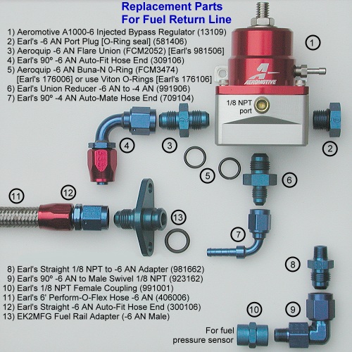
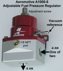
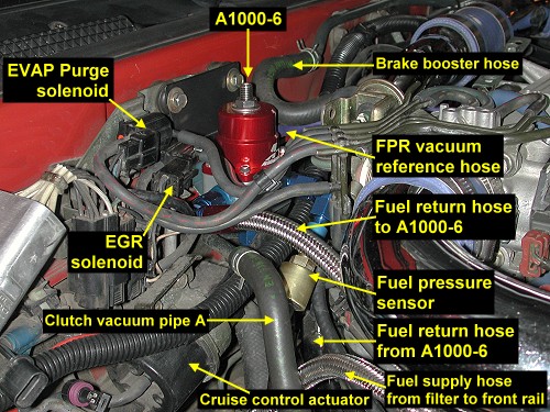
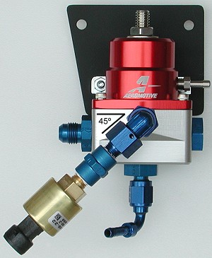
These instructions show how to remove the factory fuel pressure regulator and replace it with the Aeromotive A1000-6 adjustable FPR (part number 13109). Similar FPR's such as the SX Performance 15404 would also work. Both the A1000-6 and the 15404 have three -6 AN ports, two for fuel entering the regulator and one for fuel leaving. The A1000-6 is adjustable from 30 to 70 psi and has a 1/8 NPT gauge port. The 15404 is adjustable from 30 to 90 psi and does not have a gauge port. The SX 15402 does have a gauge port but uses -10 AN inlet ports. The A1000 is available with -10 AN ports (part number 13101). All of these FPR's increase fuel pressure 1 psi for every 1 psi of boost, the same as the factory FPR. When deciding between -6 AN or -10 AN ports and fuel hoses, remember that the factory fuel rails have an inside diameter that varies between 5/16" and 3/8" (-6 to -7 AN) and that the high-pressure fuel line from the tank to the filter is equivalent to -5 AN or -6 AN.

There are several reasons to upgrade the factory FPR. One would be because a high-flow fuel pump is installed and re-wired to receive full system voltage. The factory FPR can be overwhelmed by so much flow and cannot maintain the correct or stable fuel line pressure. Another reason would be to accommodate dual feed and return lines (one for each fuel rail). Also, you just may want a different look to the engine bay, or you may want to change fuel pressure to change fuel injector flow rate. Injector flow rate is proportional to the square root of the new pressure across the injector divided the injector's rated pressure. For example, if an injector is rated at 550 cc/min at 43.5 psi (2.96 atm or 300 kPa) and pressure across the injector is 50 psi, the flow rate of the injector is SQRT(50/43.5) times 550, or 590 cc/min (a 7.2% increase).

This web page shows how to replace the FPR and the return line from the rear (left) fuel rail to the metal return pipe down by the fuel filter. My web page 2-ek2mfg-fuelrailkit.htm shows how to replace the crossover pipe between the two rails. For tips on replacing the fuel supply line from the fuel filter to the front (right) fuel rail see my web page 2-fuelsupline.htm. Using the tips and instructions here you could design and build a dual feed and return setup for your engine.

Parts and Supplies

Fuel rail adapters 
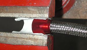
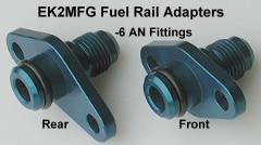
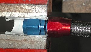
Before begining this project you will need to purchase a set of fuel rail adapters from EK2MFG (Bob Koch). Bob has these adapters built to his specifications and anodized. A of January 2004, he sells them on eBay (all four) as seller jckbkoch or you can buy them direct from him by email at ek2mfg at comcast dot net. Even a quick glance at Bob Koch's fuel rail adapters shows that these are little jewels. They are carefully and precisely crafted, and are anodized to a color blue similar to typical AN fittings. They also fit perfectly onto the ends of the fuel rail and do not leak when installed correctly. These fuel rail adapters make it simple to replace the factory supply and return fuel lines and the crossover pipe with aftermarket hoses and pipes that utilize AN fittings at the rail ends. The "front" and "rear" annotations in the picture refer to the supply and return side of the rails (where we will be working). Reverse the annotations for the crossover pipe side of the rails. The adapters come with o-rings, 1/4" split spring washers, and M6x1 socket head cap screws.

Replacement parts

You will also need an aftermarket FPR. I choose the Aeromotive A1000-6 (part number 13109) because of its price ($120 included shipping from http://www.jdsperformance.com/) and because it has the 1/8 NPT gauge port along with the -6 AN ports. To connect everything up, you will need some AN and NPT fittings as well as some hose. I used Earl's Peformance Plumbing Peform-O-Flex stainless steel braid-protected synthetic rubber hose and Earl's (owned by Holley) or Aeroquip (owned by Eaton) fittings and adapters. Russell Performance (owned by Edelbrock) also makes hoses, fittings, and adapters. If you use a different fuel hose, you will need the correct hose ends for that type of hose. The picture above identifies all the parts I used to connect the rear fuel rail to the FPR and from there to the return hose near the fuel filter. The aftermarket FPR's mentioned do not come with AN adapters, plugs, or fittings. You can buy AN and NPT fittings at the stores below either online or by phone. Shop around to compare prices and be sure to check on availability. Look in your local Yellow Pages under "Auto Peformance ..." for local shops that carry Earl's or Aeroquip fittings. That is how I found Motorsports Supply (listed below). Their prices are similar to or less than the lowest online prices and they are in the Denver, CO metro area where I live. They will ship anywhere in the USA. For online stores I recommend Summit Racing and Pit Stop USA.

       Summit Racing     Aeroquip, Earl's, Russell     http://www.summitracing.com/
       Fluid Systems Engineering     Earl's     http://www.fluidsystemseng.com/
       Pit Stop USA     Earl's     http://www.pitstopusa.com/EARAN-ANADAPTERS.asp
       Earl's Performance Products     Earl's     http://www.earlsperformance.com/
       Jeg's High Performance     Aeroquip, Earl's, Russell     http://www.jegs.com/
       Pegasus Auto Racing Supplies     NA     http://www.pegasusautoracing.com/
       American Street Rod     Earl's     http://www.amstreetrod.com/
       Tognotti's Auto World     Earl's     http://www.tognottisautoworld.com/Products/Earl/default.htm
       Behrent's Performance Warehouse     Earl's     http://www.behrents.com/
       MotorHead.com     Earl's     http://www.motorhead.com/
       ANPlumbing.com     Earl's     http://www.anplumbing.com/
       Baker Precision     Aeroquip     http://www.bakerprecision.com/aqp.htm
       Stock Car Products     Aeroquip     http://www.stockcarproducts.com/aqpindx.htm
       The Race Depot     Aeroquip     http://www.theracedepot.com/product9.htm
       Racer Parts Wholesale     Aeroquip     http://www.racerpartswholesale.com/
       Martel Brothers Performance     Aeroquip, Russell     http://www.martelbros.com/

      Motorsports Supply, 7200 E.54th Place, Commerce City, CO 80022 (phone: 303-287-1731, 1-800-288-5202)


You will have to install a fuel pressure sensor somewhere between the fuel filter and the FPR in order to correctly adjust the pressure in your new FPR. The FPR is an ideal place to mount a fuel pressure sensor or gauge. The next best place would be between the rear fuel rail and the FPR. The crossover pipe area is another option. Lastly, and perhaps the easiest and with the most room, the supply hose after it leaves the fuel filter (on its way to the front rail) is a satisfactory location. I elected to install an AutoMeter Electric Fuel Pressure Sensor, model 3363, using the NPT port on the A1000-6. You will need the adapters shown above, or similar adapters, if mounting the FPR where I did because there is no room to attach a sensor or gauge directly to the FPR. The turbo engine's dashpot and throttle cable pulley are in the way. For this particular project, you need to worry only about installing the sensor onto the FPR. Ignore the sections dealing with this sensor's installation if you are going to mount a sensor or gauge elsewhere. My web page 2-fp_install.htm has tips and instructions for mounting fuel pressure sensors. I found http://www.egauges.com/ to have the best online prices for AutoMeter gauges. I paid $185.90 (includes shipping) for the AutoMeter 3363.

AutoMeter electric fuel pressure gauge model 3363

In addition to the FPR, fuel rail adapters, fuel hose, AN fittings, fuel pressure sensor or gauge, and the optional NPT fittings, the tools and supplies required for this project include slotted and Phillips screwdrivers, pliers, utility knife, 10-mm and 12-mm sockets and wrench with 3" and 6" extensions, 10-mm open/box-end wrench, 5-mm hex key (for the fuel rail adapter screws), 3/16" hex key (for the adjustment screw on the A1000-6), -6 AN (or 11/16" open-end) wrench, 13/16" open-end wrench, 5/8" (or 16-mm) open-end wrench, 3/4" (or 19-mm) open-wrench, a bench/table vice, a sharp 32-teeth per inch hacksaw blade, duct tape, engine oil or Earl's assembly lube, a fine-tip permanent marking pen, sharp wire cutters, some paper, some string, 1/16"-thick aluminum plate, 1/4" and 3/16" drill bits and drill, a file, spray paint, Teflon tape or thread sealant if using the NPT port and a fuel pressure sensor, safety glasses, and some rags.

Costs (round numbers, no tax or shipping)
Please read all of these instructions before beginning this project, and plan ahead for parts. Once you have the (correct) parts in hand and the paint has dried on the new FPR bracket, this project should only take you a few hours.

Make and Paint New FPR Bracket

I suggest making and painting this bracket as early in the project as possible so that the paint has plenty of time to dry before you need to use the bracket. Handling the painted plate before the paint has had several days to dry will ruin the paint job. I actually made two brackets so that I would have one to practice with when installing and test fitting the FPR and other components.

Cut and drill a piece of 1/16"-thick aluminum sheet as shown below. I made the practice piece out of 1/32"-thick aluminum. For the final bracket, 1/16"-thick aluminum is preferred. You might want to try making the bottom measurement a little less than 3 inches. Work with the practice plate to determine the exact measurements and hole locations for the FPR you select and the mounting location. In fact, you may want to loosely assemble the fittings and adapters to the FPR to make sure it fits where you want to mount it. Be sure the hood will close and that the FPR and the attached fittings do not interfere with other engine components, including cables and hoses. For my selected location, I had to maneuver the return hose and the return hose fittings on the bottom of the FPR around the cruise control actuator cables. It is a tight fit, but gently pulling the cables away from the firewall allowed the FPR to fit. The cruise control actuator is identifed in one of the pictures below.

New FPR bracket plate

This plate is designed to mount to the factory bracket that holds four solenoids on the "firewall" (see below for more info). I painted the "good" one using Premium Rust-Oleum Flat Black Spray Enamel after smoothing all edges and rounding the corners with a file.

Remove Factory FPR and Return Hose

Here are the parts we need to get to: the FPR, the solenoids bracket, and the lower part of the return hose. The new FPR on its new plate will mount to the two bolts you see on the upper and right side of the solenoids bracket. The fuel pressure solenoid will be removed from the system, and the purge cannister and EGR control solenoids will be moved to the left. I am assuming that by the time you reach this level of modifications (that is, requiring or wanting an aftermarket FPR) you are using aftermarket boost control and are not using the factory boost (wastegate) control solenoid. Note in the lower picture that I have removed the high-pressure fuel supply line that connects to the top of the fuel filter. This is not necessary as part of this project. Also, note that I have moved my battery to the rear compartment area. The factory battery tray and washer tank are still in their original locations, though.

Factory FPR location    Factory FPR

Solenoids bracket

Lower return hose

1. Relieve fuel line pressure. In the rear storage compartment, remove the carpet (velcro and push-in clips) and particle board floor (4 Phillips screws), or just raise these up out of the way. Remove the spare tire. Remove the passenger's-side storage bin (3 Phillips screws). Remove the access cover to the fuel pump (4 Phillips screws). Separate the electrical connector by pressing down on the tab and pulling that piece toward the front of the car. You do not need to remove the blue filter as suggested in the picture below. In the upper picture, the wires shown running under the assembly cover are part of my fuel pump re-wire and are not present on a factory setup. Try to start the engine. It should not start because the fuel pump has no current to it.

Remove the negative cable from the battery. Be sure you have any security codes that might be needed when the battery is disconnected.

Fuel pump assembly cover    Fuel pump wiring harness connector

2. Move items out of way near factory FPR. To get good access to the factory FPR and that end of the rear fuel rail I moved several components and tied them out of the way with string, including the PCV hose, CAS connector (1991-1992 models only), and the triple clamp on the plenum. I also removed the air filter and the MAS for my ARC2 air intake to avoid possibly damaging the air filter while working in this area.

Clearing items away from factory FPR

3. Remove the battery and washer tank. Follow the instructions and tips on my web page 2-batteryout.htm to remove the battery, tray, and washer tank. This will give you good access to the bottom end of the fuel return hose.

4. Remove fuel return hose. Place a rag under the hose to catch gasoline that remains in the rails, pipes, and hose. This gasoline should not be under pressure. However, as a precaution wear safety glasses to protect your eyes when removing the hose. Because gasoline contains carcinogens such as benzene, avoid letting the gasoline contact your skin. And, of course, do not ingest gasoline and avoid breathing fumes. Gasoline is poison as well as a fire hazard. Use pliers to loosen the clamp and slide it off the hose onto the pipe. Leave the clamp there because we can re-use it. With the pliers gently twist the hose and pull it off the metal pipe. Similarly, remove the return hose from the factory FPR, except slide the clamp down the hose. Save the clamp because we can re-use it to attach this hose to the new FPR.

The fuel return hose can be re-used, after being shortened, with the new FPR. The hose has a protective plastic sheath around it. This sheath was hardened in some places due to exposure to high heat levels. There is a clamp about mid-way on the hose that holds the hose close to the supply hose and the engine. Either slide the return hose through this bracket or remove the bracket. If you are replacing the supply side hose also, then do what you need to free that hose and pipe (banjo bolt at filter and attachment to front rail) and remove both lines at the same time. This factory return hose in the engine bay is re-inforced rubber (of some sort) with a 7/16" (11.1 mm) outside diameter and a 7/32" (5.56 mm) inside diameter. That ID is equivalent to a -4 AN metal tube.

5. Remove factory FPR. Remove the vacuum hose on the top of the FPR. Remove the two 10-mm hex cap screws that attach the factory FPR. Pull the FPR slowly but firmly away from the engine to remove it. You may need to twist or wiggle it a little. I measured the opening of the FPR into the rail as 7/32" in diameter (typical for -4 AN tube). The EK2MFG adapter's opening is 10/32" (8 mm or 5/16", the typical -6 AN tube inside diameter).

FPR in place


6. Remove factory solenoids. The firewall area is a convenient location to mount a relatively large FPR such as the Aeromotive A1000-6. The solenoids bracket is ideal. It is cushioned in its mounting to the firewall and it has sufficient area around it, including enough clearance when the hood closes, to install the A1000-6. The picture below shows the completed installation so you can see where we are headed.

A1000-6 installed

The fuel pressure control solenoid (or valve) is used by the engine control unit (ECU) only to increase fuel pressure during hot engine starts when there is a greater possibility of fuel vapor being generated in the fuel lines. When the air intake temperature exceeds 140ºF (60ºC) and the engine coolant temperature exceeds 194ºF (90ºC), the ECU uses the fuel pressure control solenoid (for up to two minutes) to allow outside air into the vacuum hoses to increase fuel pressure. In addition, the ECU increases fuel injector activation duration (richens the mixture). These two actions by the ECU are what I believe is a cause of the hot-engine hard-start condition I and many others have experienced on a hot summer day after turning the engine off for a short while. The engine acts like it is flooded for maybe a minute then runs fine. Because this is the only purpose of the fuel pressure control solenoid, I decided to remove it. I don't think there is much we can do about this part of the ECU programming short of going to stand-alone engine management. Owners that have removed the fuel pressure control solenoid, whether upgrading to an aftermarket FPR or not, have not reported problems related to this. I will update this web page if I encounter problems. If you decide to keep this solenoid, you need to modify the instructions that follow.

Identify the fuel pressure solenoid and the hoses that attach to it (see the picture above at the beginning of this section). There is a hose that goes from the nipple on the back of the plenum to the rearmost tube on the throttle body, and a hose from the other end of that tube to the solenoid. There is another hose that goes from the solenoid to a different tube on the throttle body, and a hose from the other end of that tube to the FPR. Remove these hoses, being careful to not disconnect any other vacuum hoses. Disconnect the wiring harness from the solenoid (identify the release lever and press it while tugging on the connector). Look at the way the fuel pressure solenoid slides into a "forked" bracket on the larger solenoids bracket. Press "back" ( toward the firewall) on the lip and at the same time press "down", that is, to the left, to slide the solenoid off its bracket. A screwdriver or similar tool can help. Do not press on the solenoid where you might break off one of the hose nipples.

Leaving the hoses and wiring harness connected to the purge control and EGR control solenoids, remove them from the solenoids bracket, and move them to the left of the bracket. After the final mounting of the new FPR and its plate to the solenoids bracket, you will put these two solenoids back on, but in different locations. Of course, if you are not using the EGR system or purge cannister (a charcoal cannister that filters fuel tank vapors), these solenoids and their hoses can be removed and the vacuum lines capped.

Install the New Parts

1. Install the fuel rail adapter. Apply a small amount of engine oil to the o-ring for the EK2MFG fuel rail adapter and roll the o-ring onto the non-threaded end of the adapter. There is a recess for it to rest in. See the picture of the adapters near the top of this web page. Wipe the end of the fuel rail clean. Be sure no dirt or particles have entered the fuel rail or the adapter. Apply a little more oil to the o-ring and firmly, but slowly and evenly, press the o-ring end of the adapter by hand into the rail with the mounting holes lined up. Again, you may need to twist or wiggle the adapter very slightly to insert it completely into the fuel rail. If you are worried about dropping the adapter during this process, tie a length of string to the threaded end of the adapter and/or place a shop towel under the rail. Put the split spring washers on the socket head cap screws and start the screws by hand several turns into the rails. Tighten the screws using a 5-mm hex key. It is the o-ring that seals the adapter to the fuel rail, not the face of the rail or the adapter. If you are worried about dropping the hex key, tie a piece of string to it to facilitate retrieval if necessary. Be very careful to not drop the adapter, the mounting screws, or the hex key into the abyss under the rails and plenum.

Fuel rail adapter installed

2. Build the FPR assembly and (temporarily) install. AN fittings seal either by the close contact of the 37º flared ends or with o-rings. The threads themselves never seal AN connectors. Also, never use thread sealant or tape on AN threads. Because there is no flared base in the ports on the A1000-6, o-rings are required to make a seal. You can buy a package of ten -6 AN o-rings from either Aeroquip or Earl's. Either BUNA-N synthetic rubber or Viton will work. Both compounds are compatible with most fuels. However, Viton is more scuff resistance, can last longer, and has a higher temperature rating (400ºF instead of 275ºF for the BUNA). I wasn't paying attention when I ordered the BUNA o-rings shown above. The Viton o-rings are a better choice for this project.

Install the -6 AN port plug on the right side of the A1000-6. The port plug should have come with an o-ring on it. If not add one. Start the plug by hand and tighten it by hand as far as you can.

The -6 AN flare union will not come with an o-ring so you will need to add one. Rub a little bit of engine oil on an o-ring and roll it onto the threads on one end until the o-ring rests against the flat hex portion of the union (past the threads). By hand, thread the end of the union that has the o-ring into the left port on the A1000-6.

The factory return hose is too small to fit onto a -6 AN Earl's Econ-O-Mate hose end. It will, however, slide easily onto a -4 AN Econ-O-Mate hose end. Maybe just a bit too easily; so you will need a clamp to secure a seal. The -6 AN to -4 AN union reducer will not come with an o-ring so add one to the -6 AN side. By hand, thread the union reducer into the lower port of the A1000-6. Add the 90º -4 AN Econ-O-Mate hose end to the reducer and tighten by hand. The female swivel on the hose end allows you to align the hose end in the desired direction. Once the female swivel is properly torqued onto the union reducer, the hose end will not swivel. For now, just hand tighten everything because you need to practice installing the assembly to get the best alignment for the Econ-O-Mate hose end and the fuel pressure sensor adapters if used, and to measure the two return hoses for length.

If you are going to mount a fuel pressure sensor to the A1000-6, assemble the adapters and fittings as shown by hand and without tools or thread sealant. By hand, add the sensor. For now, you really don't need to remove the NPT port plug in the A1000-6. You can just hold the NPT fittings and sensor up to the FPR to test for fit and orientation.

Attach the assembly to the practice bracket and attach the practice bracket to the solenoids bracket using the upper two bolts on the solenoids bracket. You will have to move the cruise control actuator cable a little to get the lower return hose fittings past and below the cable. Position the lower fittings so you have clearance for the lower return hose and try to tighten the fittings a little by hand to fix their positions. Do the same thing with the pressure sensor fittings. Also, add the 90º Auto-Fit hose end to the assembly and the straight Auto-Fit hose end to the fuel rail adapter and tighten by hand.

Now, measure the two return hoses for length. I place the hoses in their respective positions and routings to do this. The upper hose needs to fit comfortably between the rear fuel rail and the hose ends. The hose will extend about to the "far" end of red socket on each hose end. Add a piece of tape to mark where you need to cut the hose. Slide the lower return hose onto the metal tube by the fuel filter and route it over towards the FPR. Determine the right length for this hose and mark with a piece of tape. I cut this hose 17.75" long. The exact length will depend on where you route the hose and mount the FPR. Do not cut the hoses just yet. Once you are satisfied with the hose lengths and fitting positions, remove the FPR assembly and its plate from the solenoids bracket, trying to not disturb the alignment of the fittings.

The pictures below show the A1000-6 attached to the painted plate using 8-32 screws and nuts. I allowed a week for the paint to dry. I found it easier to attach the lower return hose to the Econ-O-Mate hose end, with the factory spring hose clamp, before installing the completed assembly in the engine bay. This requires some careful maneuvering around the cruise control cable. But it is easier than trying to attach the hose and clamp afterwards. For now, leave the assembled FPR without hoses on the temporary (practice) plate. Once you have the hoses made and are ready for the final installation, attach the completed FPR assembly to the painted plate. The idea is to attach the FPR to the painted plate, and the plate to the solenoids bracket, only once to minimize marks and wear on the plate.

The angles shown below worked for my setup. The position of the fitting may be a little different for your setup. When you are ready for the final assembly of the fittings and adapters to the FPR, use a wrench to tighten the plug and unions until they bottom out against the A1000-6. There is a recess in the port opening to receive the o-ring; you are not crushing the o-ring (look carefully at the port in the picture of the A1000-6 at the top of this document). Then, using one or two wrenches tighten all the AN fittings and adapters. You only need to use 10-12 ft-lbs of torque on these aluminum fittings.Do not over torque them. However, for the 90º hose ends, you will not be able to move or adjust the angle of the fitting after the swivel end is properly torqued. If you can still move the hose end, tighten the swivel end some more.

If using a fuel pressure sensor, clean the NPT threads and assemble these fittings and adapters, using thread sealant on the NPT threads. Apply the sealant where you have determined the threads will mate. Do not apply sealant to the first or second thread near the opening of the fitting. You do not want sealant inside the sensor, FPR, or fittings. Follow the instructions provided with the thread sealant. Some time may be needed for the sealant to dry after assembly. Go ahead and attach the these fittings to the FPR, after removing the port plug with a 3/16" hex key, if you are ready for the final installation, again using thread sealant.

A1000-6 assembled front    Thread sealant

A1000-6 assembled bottom


3. Make upper return hose from rail to FPR. Earl's Performance Plumbing Perform-O-Flex hose is an excellent replacement for the factory fuel hose in the engine bay. The figure below is from Earl's 2003 catalog.

Earl's Perform-O-Flex hose

The proper way to connect Earl's braid-protected hose is to attach the correct hose ends that will match the AN fittings on the fuel rail pressure adapter and the FPR. Earl's recommends using their Swivel-Seal, Auto-Fit, or Auto-Mate hose ends. I used Earl's anodized Auto-Fit hose ends. These are available also as unanodized polished aluminum. Earl's provides excellent instructions for putting hose ends on their hose. Rather than trying to re-write these, I present a copy of their instructions.
Earl's Perform-O-Flex hose-end instructions
Here are some pictures of the hose end attachment process. This first picture is of one of the first hose cuts I made. It looks bad but it does trim up to work just fine. Later hose cuts were better. Be sure to wrap several turns of duct tape tightly around the hose. I used a piece of paper to protect the fittings from the steel vice jaws. In step 2, I used my fingernails to poke any short braid strands into the socket as I rotated the hose into it. After the hose is inserted all the way, and pulled back a small amount, be sure there are no loose braid strands that could enter the hose after assembly. In step 4, hold on to only the hose until the socket is started onto the nipple. Don't be afraid to use plenty of oil when assembling the parts. If the socket just will not start, pull the hose back a very small amount in the socket and try again. Be careful when starting the socket onto the nipple. I mildly cross-threaded one. I had an extra hose end so I just put the new socket onto the hose and started over - a bit more carefully. In step 5, you will need a 3/4" (or 19 mm) open-end wrench to tighten the red socket onto the nipple.

hose cut    hose trimmed

socket in vice    nipple in vice

completed hose end

completed hose

4. Make lower return hose from FPR. I re-used the factory return hose by cutting it to fit and then trimming back the protective, outer, plastic sheath about 2 inches. If you are going to use a new hose, select one that is resistant to fuels, is thick-walled, and has an inside diameter of about 7/32" (5.56 mm). If you want to match the upper hose, Earl's Peform-O-Flex hose in -4 AN size has an ID of 7/32" and OD of 7/16". Screw-type hose clamps should work to secure the hose to the FPR and to the metal factory return tube.

5. Attach the hoses. If you have not made the final attachment of the FPR and its painted plate to the solenoids bracket, do so now. Be sure you cannot rotate by hand the 90º -4 AN Auto-Mate hose end on the bottom of the FPR. Also, I found it easier to attach the lower return hose to the Auto-mate hose end with the factory spring clamp before installing the FPR. Route the upper hose through the engine bay and connect each end, straight hose end at the fuel rail. Always start these fittings by hand and do not use a wrench until you can no longer turn the fitting by hand. Do not use excessive torque on these aluminum AN fittings. Ten to 12 ft-lbs is sufficient. The seal is made at the 37º flared end, not in the threads. Route the lower hose onto the metal return tube and slide the spring clamp onto it.

Connect the vacuum reference hose from the back of the plenum to the upper nipple on the FPR. This hose has an ID of about 1/8" or 3 mm. I used aftermarket blue silicone hose but you could use a piece of the vacuum hose that originally connected the nipple on the plenum to the factory FPR.

6. Pressure test. Double check that all the fuel lines are connected up. Re-connect the harness connector at the fuel pump in the rear storage compartment. Use the fuel pump check terminal to supply voltage to the fuel pump to pressurize the lines before starting the engine. If your battery was installed in the engine bay, bring it over close to the engine, perhaps sitting it on a table, bench, or chair. Remove the cap from the fuel pump check connector and insert a small paper clip. Connect a small-gauge jumper wire (14 to 18 ga is fine) with alligator clips on the end to the paper clip and to the positive battery terminal (or just touch the jumper wire to the battery positive terminal). Be sure you protect the positive cables from contacting the car body or anything metallic in the engine bay. Use a car jumper cable to connect the negative battery terminal to either the negative battery post or other good ground location in the engine bay. You should hear the fuel pump running. Carefully inspect your work for leaks - look and smell. Repair or rebuild any connection that leaks and repeat this test. I encountered no leaks.

If your battery has been moved to the rear compartment or you have re-wired the fuel pump directly to the battery, you will have to connect the battery to the positive and negative cables in the engine bay or rear compartment so that the fuel pump has current to it. You will still need to connect the fuel pump check connector as described above. Because my battery is in the rear compartment, I used my old Dyna-Batt to supply current to the check connector as shown in the lower picture below. I connected one end of the negative (ground) jumper wire to the firewall ground screw and one end of the positive jumper wire to the fuelpump check connector. I then just touched the ends of the jumper wires to the correct terminals on the battery.

If you have a mechanical fuel line pressure gauge connected you can adjust the FPR to set the desired fuel line pressure now (see next section).

Check connectors

Fuel pump check connector

Post-installation

1. Put stuff back. Reconnect any hoses or harness connectors and brackets you have disconnected. Re-install the battery tray and washer tank, being sure to reconnect the harness at the washer pump before you have lowered the tray completely and to reconnect the harness up by the check connector and the fluid tube. Re-install the MAS and air filter if removed (don't forget to re-connect the MAS wiring harness). Install the battery, connecting the negative cable last.

2. Set the fuel line pressure. You must have a fuel pressure sensor or gauge connected to adjust the FPR to set the fuel line pressure. The sensor or gauge must be connected to the FPR or be tapped into the fuel line between the fuel filter and the FPR. You need a 3/16" hex key to adjust the screw on the A1000-6. Loosen the lock nut at the base of the adjustment screw. I found that turning the screw 1/2 turn clockwise increased fuel line pressure by 5 psi. Remove the vacuum reference hose from the plenum or A1000-6. Start the engine and adjust the fuel line pressure.

According to the 1999 3000GT Service Manual, for the turbo DOHC models, the pressure should be 295 to 315 (42.7 to 45.6 psi). I set mine to 43 psi. For the SOHC and non-turbo DOHC, the pressure should be 330 to 350 kPa (47.8 to 50.7 psi). With the engine still running, re-connect the vacuum reference hose. The fuel pressure should reduce by about 7 to 10 psi, depending on your elevation and vacuum at idle. My fuel pressure reduced to 36 psi, corresponding to the 365-385 mm Hg (14.3-15.1 in. Hg, or 7-7.4 psi) vacuum my engine usually maintains at idle here at 5600 feet above sea level. If your engine holds 18 to 20 in. Hg (457 to 508 mm Hg), then your fuel pressure should drop 8.8 to 9.8 psi with the vacuum hose connected. You can use the Unit Converter calculators on my web page 2-converters.htm to convert between psi and other units of pressure. After you have the pressure set, keep the A1000-6 adjustment screw from turning with the 3/6" hex key and tighten the lock nut with a 9/16" wrench.

Catalogs

Earl's 1999 Product Catalog (14 MB): misc/earls_full_catalogue.pdf
Parker Fluid Connectors pipe fittings and adapters catalog (0.9 MB): misc/pipe_fitting_and_adapters.pdf
Truechoice catalog (8.5 MB); go to page 100 for Earl's fittings and adapters: misc/truechoice_catalog.pdf
Essex Parts catalog (2 MB): misc/earl's_fittings&hoses.pdf
Russell Performance Automotive Catalog: http://www.russellperformance.com/automotive/autocatalogpdf.htm


Back Home Forward

Except for the small gif and jpg images, the content, images, photographs, text, and multimedia displayed are Copyright © 2000-2009 by Jeff Lucius and K2 Software. All rights reserved. No part, section, image, photo, article, or whole of this site may be reposted or redisplayed without permission of the authors.
Page last updated August 30, 2009.