Fuel Pump Re-Wire in the
Mitsubishi 3000GT/Dodge Stealth
by Jeff Lucius
Introduction
It is critically important that the fuel pump receive the maximum amount of voltage available from the charging and wiring system. The alternator will try to maintain about 13.5 volts into the system. Resistive losses along the current path to the pump will reduce the voltage at the pump to something less than 13.5. If there are less than 12 volts at the pump, the amount of fuel flowing may be much less than expected and perhaps enough less to create lean air-fuel mixtures under heavy acceleration. The instructions below show how to re-wire the fuel pump directly to the battery. Please read through the instructions and look at the pictures before attempting this procedure. For other tips on re-wiring the fuel pump, please take a look at Bryan Rogers instructions at 2-fuelpump-hotwire.htm.
Erik Gross offers a different and much easier method to increase the current to the fuel pump on his web page http://www.supercar-engineering.com/rubberducky/3S/Mods/TT/FPRewire/index.html. Erik shows how to provide current direct to the factory fuel pump relay for the resistor, rather than running a new wire direct to the pump. Erik's method provides increased voltage (system minus ~1 volt) to the pump when the resistor is by-passed by the ECU, yet maintains low voltage to the pump during idle and low-load cruising. If you also add the optional heavy-gauge wire from the factory relay to the pump (an option that Erik shows in his diagrams) there should be close to system voltage at the fuel pump except at idle and low-load cruise (the best of both worlds!).
Before I re-wired the fuel pump in my 1992 Stealth Twin Turbo, I measured the voltage at the pump using the method shown on my web page 2-fuelpumpvoltage.htm. At idle the pump was receiving about 6.7 to 7.0 volts (turbo models use a relay and resistor to lower the voltage at idle). I saw from 10.6 to 10.8 volts as boost began to build and then watched that number drop to 10.2 to 10.3 volts as boost hit 15 psi or so and RPM approached redline. I bypassed the relay/resistor (2-fuelpumprelaybypass.htm) and re-measured the voltage at the fuel pump with the following results.
Cold idle: 11 volts
Warm idle: ~10.6 volts
Warm idle after radiator fan kicked in: 10.35 - 10.55 volts
Acceleration and boost: ~10.5 volts
After taking the measurements above, the voltage at the battery during warm idle was 13.72 volts, which is normal for a properly functioning alternator. The "resistor bypass mod" did not improve voltage to the pump for me. Other owners do report voltage increasing to the 11.5 (acceleration) to 12 (idle) volts range. Perhaps there is increased resistance at some point in the fuel pump electrical circuit in my car, such as at the grounding point. I had moved the battery to the rear compartment and so I ran a new ground cable from the fuel pump assembly directly to the battery to see if this would make a difference. It did not. The voltage at the pump did not change because the fuel pump is grounded to the pump assembly frame which had a good ground directly to the body/frame through the fuel tank.
I next performed the re-wire shown on this web page. After the re-wire, the voltage at the pump was about 0.11 volts less than the battery voltage. Success! This success came with a consequence though. At idle, the Supra Turbo fuel pump I am using flows too much fuel at this voltage level for the stock fuel pressure regulator to handle. My idle fuel pressure shot up to 38 to 47 psi (depending on voltage and temperature). This is not too big a deal as the pressure still rises with boost (~60 psi at ~15 psi boost) and I can adjust the ARC2 to compensate (if necessary) for the slight increase in fuel flow. Still, I will investigate finding an aftermarket replacement for the FPR to maintain a more stable fuel pressure.
The tools and supplies needed include a Phillips screwdriver, wire cutter and crimping tool, utility knife, electrical tape, about 20 feet of 6-gauge or 8-gauge insulated, multistrand wire (if the battery is in the engine bay), some butt-splice or quick disconnect terminals (2-crimpterms.htm), a 30-amp fuse and holder, and a 30-amp relay with a relay socket.
Fuel pump electrical circuit
Looking at the circuit diagrams in the service manual, I found the following current path to the pump for turbocharged models.
1) Battery [+ terminal]
2) Fusible link [30A - terminal 4]
3) Ignition switch [IG1]
4) Multipurpose fuse [15A - terminal 12]
5) Engine control relay
6) Fuel pump relay 2 (turbo models only)
6a) Resistor [switched by ECU at idle through the pump relay]
7) Fuel pump
8) Chassis ground [-] through fuel pump assembly frame to gas tank to body/frame
Summary
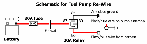
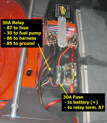
If all you need are pictures then look at these two and go add the new circuit. I recommend using 8-ga or thicker wire to connect the 30-amp fuse (near the battery in the engine bay) to the 30-amp relay (near the fuel pump). Note that connections at relay terminals 85 and 86 can be reversed; same for terminals 87 and 30 (that is, it makes no difference which direction the current flows). For more detailed instructions and additional information please continue reading.
Preparation
1. Plan the work. The schematic above shows what you basically need to do. A 30-amp fuse (a 20A fuse might work with the stock pump) must be wired close to, or directly to, the battery. Then you need to run a heavy-gauge wire (6-ga or 8-ga) from the fuse to a 30-amp relay near the fuel pump. There are two access holes in the firewall you can use, one near the battery and one near the steering column (2-dashpanelaccess.htm). The 30-amp relay (higher rated amperage is OK) connects directly to (or with short jumpers to) the fuel pump wiring.
To determine what size wire you need to run between the fuse and relay, or even between the relay and fuel pump, you need to decide how much voltage loss is acceptable for the expected current draw, how long the wire is, and what the resistance of the wire is per foot (or per meter). My web page 2-wire-resistance.htm shows the resistance per 1000 feet for wire gauges commonly found in automobiles and provides a calculator for determining voltage drop along a length of wire for a given amperage draw. The shortest practical path between the stock battery location and the fuel pump (through the harness opening near the battery and along the door sill) is about 12 feet. Add maybe 5 to 6 feet if you choose to go through the firewall opening near the steering column. Fuel pumps draw from 10 to 20 amps or so depending on the fuel line pressure (higher line pressure means higher current draw). For a cable 12 feet long and a current draw of 20 amps, voltage will drop about 0.24 volts using a 10-ga cable, about 0.15 volts using an 8-ga cable, and about 0.10 volts using a 6-ga cable. For my design, I wanted less than 1 percent voltage drop (less than 0.135 v) between the battery and fuel pump.
2. Purchase the supplies. There are three items you need that may not be available locally: a 30-amp fuse holder, a 30-amp relay with a socket, and 6-ga or 8-ga wire. Some auto parts stores carry inline fuse holders and relays, but the cable may be hard to find. Fortunately, these three items can be available at auto sound shops and suppliers. If you need to, or prefer to, buy on-line, the supplies you need can be purchased at the following web sites.
http://www.partsexpress.com
http://www.sounddomain.com
http://nexxon.com
http://www.jcwhitney.com
http://www.hosfelt.com
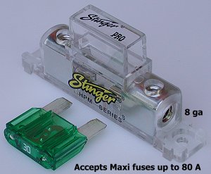
You need a fuse to protect the battery and car from any potential problem in the new circuit you will be making. The fuse holder I chose (see picture below) is designed to mount on the battery shelf I made to fit behind the rear seat. A simple inline fuse holder works fine for a battery mounted in the engine bay.
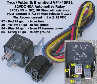
You need a relay to turn the pump on and off using the same stimulus as the stock wiring: the engine cranking or running. The relay uses the stock power line to switch the new circuit you are making on and off. Be sure you purchase a relay socket to go with the relay you select. Otherwise, you are faced with the time-consuming task of making secure and insulated connections to the relay terminals. Popular relays include the Bosch 0 332 204150 (available with a relay socket from http://www.partsexpress.com), the Tyco/P&B VF4-45F11 (available with a relay socket from http://www.hosfelt.com), the Radio Shack 275-226 (no socket available), and the Hella 960 388 07. http://www.jcwhitney.com also sells a relay and socket. Any 30A automotive relay will work. For more information about relays (such as what NO, NC, and SPDT mean), look at the following web pages.
http://www.mgcars.org.uk/electrical/body_relays.html
http://www.eatel.net/~amptech/elecdisc/relays.htm
http://www.take5-net.com/toronado/relay.htm
http://www.autoshop101.com/forms/hweb2.pdf
Those of you knowledgeable about relays are probably wondering if you need to add a quenching/suppression diode in parallel with the relay coil. I don't believe this is necessary. The factory MPI circuit (which includes the engine control relay and the fuel pump circuit) is protected by a diode located in the driver's side foot well area (see the service manual for the exact location). The new circuit you are adding basically just connects the fuel pump to the battery. There are no switch contacts or power switching transistors in this new circuit that could be affected by the reverse voltage (called inductive kickback or back EMF) generated when the relay coil's magnetic field collapses when power is removed.
3. Battery. With the ignition off, remove the negative battery cable from the battery. Be sure you have security codes for any devices that might need them before you do this. If you plan to run the heavy gauge cable through the firewall at the harness access near the battery, you may want to remove the battery from the car to make it easier to work in that area.
4. Resistor Bypass. The relay is a switch. When the relay is "on", the current flows through the new heavy gauge wire you will be installing and to the fuel pump. The old power wire to the fuel pump turns this switch (the relay) on and off. A minimum voltage must be supplied on the switching circuit (the old fuel pump power wire connected to either terminal 85 or 86 on the relay) to activate the relay. This minimum voltage, called the pick-up voltage or pull-in voltage, increases with the temperature of the relay. At 20ºC (68ºF), the P&B VF4-45F11 relay has a pull-in voltage of about 6.5 volts. Bosch automotive relays have a typical pull-in voltage of about 8 volts. Because the resistor utilized in the turbo models lowers the voltage to the fuel pump to about 7 volts or less, you may need to bypass this resistor in order for the new relay to function. I have instructions for this at 2-fuelpumprelaybypass.htm. You can try not bypassing the resistor but if your fuel pump does not run after completing the rest of this re-wire modification, suspect the voltage is too low to switch the relay "on".
5. Rear compartment. Remove the carpet (velcro and push-in clips) and particle board floor (4 Phillips screws) from the rear compartment. Remove the spare tire. Remove the passenger's-side storage bin (3 Phillips screws).
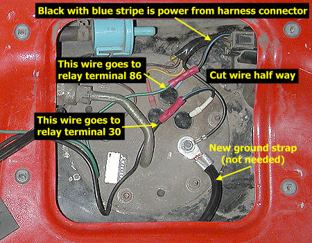
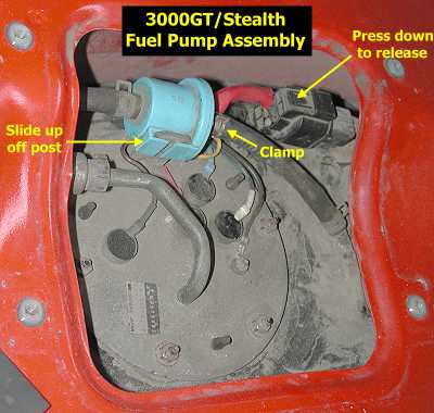
6. Gain access to the pump wires. Remove the access cover to the fuel pump (4 Phillips screws). Pinch the spring clamp on the vent hose that leaves the blue valve toward the back of the car and slide the clamp off the valve. Lightly grasp the hose and twist it a little to break its seal on the valve nipple. Slide the hose off the nipple and bend the hose out of the way. Slide the blue valve up off the post. Separate the electrical connector by pressing down on the tab and pulling that piece toward the front of the car.
Add the new circuit
1. Fuse. Connect a 30-amp fuse to the battery positive terminal. I had moved my battery to the rear compartment before re-wiring the fuel pump, so I used the fuse holder pictured above. I connected the fuse holder to the battery terminal using a short piece of 8-ga wiring. This is admittedly a much larger wire than necessary for this short a length. When the battery is mounted in the engine bay using the stock battery terminals, add a ring connector (2-crimpterms.htm) to one of the fuse holder wires and attach the connector to the post on the battery positive terminal (the "alternator wire" is attached to this post using a ring connector).
2. Run the heavy-gauge wire. When the fuse is more than a meter from the relay, a heavy gauge wire must be run between the two. With the battery and fuse in the engine bay, connect the 6-ga or 8-ga cable to the remaining fuse wire or the fuse holder and route the cable through the firewall as discussed above. Run the wire under the carpet near the base of the doors (remove the plastic scuff plate and cowl side trim at the base of the door opening so the carpet can be lifted). Remove the rear seat cushion (pull forward on the two levers to release the cushion and pull the cushion up and forward), and route the wires under the cushion and to the fuel pump.
Because I moved my battery to the rear compartment, this heavy gauge wire was not required. The relay is only an inch or so away from the fuse and the fuel pump is less than two feet away from the relay. I used the calculator on my web page 2-wire-resistance.htm to determine that two feet of the 14-ga wire used on the relay socket would have a voltage drop of only 0.10 volts with a 20-amp load. This is less than my 1 percent (or 0.135 volt) voltage loss requirement for my new circuit.
3. Connect the relay. If the battery and fuse are in the engine bay, either mount or place the relay near the fuel pump. There is room between the spare tire and right storage bin for the relay to rest (perhaps secured to the body with duct tape). The relay can also be close enough to the fuel pump to rest on the fuel pump housing so only the heavy gauge wire passes through under the assembly access panel. Look at Bryan Rogers' instructions for this type of arrangement: 2-fuelpump-hotwire.htm. Bryan also did not use a relay socket and chose instead to solder the wires directly to the relay terminals.
Connect the wire from the fuse to the wire on the relay socket that goes to relay terminal 87. Select the appropriate type of terminal from the choices shown on (2-crimpterms.htm).
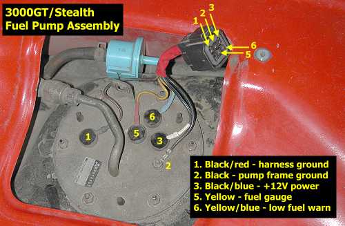
Cut the black wire with a blue stripe half way between the harness connector and the fuel pump (see the picture above in the summary section). Strip about 1/4 inch of insulation off each end of this wire. If you might want to reverse this re-wire modification in the future, then connect a male quick disconnect to one these wires and a female quick disconnect to the other wire. This way they can be unplugged from the relay and plugged back together. In any case, connect these two wires to the relay, either directly or using short jumper cables. The black wire with a blue stripe from the top of the fuel pump assembly connects to relay terminal 30. The black wire with a blue stripe from harness connects to relay terminal 86. If you want to measure the voltage at the fuel pump, then leave about 1/8" of the wire from the top of the pump assembly exposed near the connector (or relay). This will be wrapped with electrical tape later after the voltage is measured.
Connect relay terminal 85 (or the wire on the socket that connects to terminal 85) to any close grounding point. The post on the pump assembly indicated in the pictures above is perfect. At this point your new circuit is complete.

4. Test the circuit. Reconnect the negative battery terminal and cable (be sure that the short section of exposed wire near the pump to measure voltage is not grounded). Look and listen for any problems. If a fuse blows or there are any sparks or unusual noises, smells, or smoke, immediately (if not sooner) disconnect the negative battery cable. Find the problem and correct it. Once every thing looks fine, start the engine. Using a volt-ohm meter, compare the voltage at the pump (use that short section of exposed wire and the ground post on the pump assembly) and across the battery terminals. During idle after the engine warmed up, I had 13.86 volts across the battery terminals and 13.75 volts at the fuel pump. The small 0.11 voltage drop is just what I predicted using the short sections of 14-ga wire in my setup and less than the 1% maximum loss I wanted in my design.
5. Close things up. For protection against dirt and moisture, wrap all your crimp-on connectors and the wire near them with electrical tape (or shrink tubing if you had planned ahead and slid some onto the wires), especially that short exposed section of wire for use in voltage measurements. I needed to put a small "bump" in the fuel pump access panel for the thick wires to go through. The cover is easily bendable if you need to do this also. Put the rear compartment items back in.
Be sure to check the fuel pressure if you are using a larger-capacity-than-stock fuel pump (2-fp_install.htm).
Page last updated April 9, 2003.