A'PEXi S-AFCII Installation in the
Mitsubishi 3000GT VR4 & Dodge Stealth TT

by Jeff Lucius

   Topics
         
Introduction
Reality Check
Wiring Diagrams
Getting to the ECU
Tapping into the ECU Wires

Introduction

A'PEXi S-AFCII control unit 
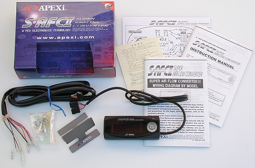
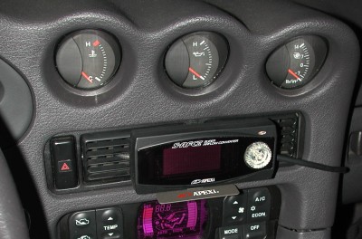
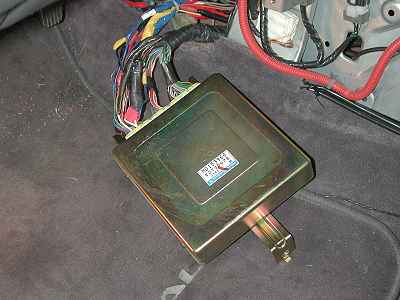
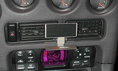
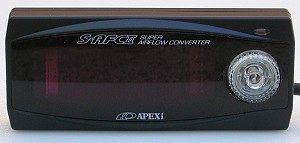
These instructions will help you install the A'PEXi S-AFCII Super Airflow Converter in the Mitsubishi 3000GT VR4 and Dodge Stealth R/T Twin Turbo. The control unit pictured to the right is the "black on black" model. Other color combinations are available: silver case with blue display, silver case with black display. These web-page instructions are specifically for the 1992 3000GT/Stealth DOHC Turbo. However, they can be used for all other DOHC model years by selecting the correct engine control unit (ECU) wires for the target 3S model. In addition, my 1992 Dodge Stealth TT already had an ARC2-GP hot-wire mass airflow sensor (MAS) conversion installed (as well as other electronics that tapped into the ECU harness). The S-AFCII was installed inline "after" the ARC2-GP. For instructions about how to adjust the S-AFCII see my web page 2-safcii-adjust.htm.

The S-AFCII intercepts the air flow signal (volume or mass) and increases or decreases it before the engine control unit (ECU) "sees" the signal. This can be used to compensate for larger-than-stock fuel injectors and to fine-tune the air-fuel mixture. The S-AFCII can be used with engines that have a "hot-wire", "flap", or pressure mass air flow sensor (single or dual), or the Karman-type volume air flow sensor, which is installed on 3000GT/Stealth (3S) engines. I am not sure how, or if, the control unit can distinguish between a frequency-based hot-wire MAS (for example many GM MAS's) or a voltage-modulated hot-wire MAS (for example many Ford MAS's). In any case, these instructions assume the S-AFCII is intercepting a Karman-type volume air flow signal. Therefore, it can be used with the stock 3000GT/Stealth MAF or after a hot-wire conversion (ARC2-GP, MAF-T, PRO-M). The S-AFCII cannot be used to convert a mass flow signal to a volume flow signal, that is, it cannot be used to convert the signal from a Ford or GM MAS to the Karman signal required by our ECU. For our car, the signal going into the S-AFCII must be a Karman signal (a frequency modulated square-wave) so that the S-AFCII sends a Karman signal to our ECU.

The A'PEXi S-AFCII "kit" consists of the items shown in the photograph below: the control unit, a wiring harness, manuals and instructions, a mounting bracket, some electric coupling pieces, and a little bit of Velcro. I paid $300 (includes shipping) for this black case/black display special edition model from seller tri-band-mobile (also a 3000GT owner) on eBay in August 2003.

A'PEXi S-AFCII kit


The A'PEXi S-AFCII is an airflow signal converter that has the following features and functions when installed on our DOHC models, which send a Karman-type airflow signal to the ECU.
The tools and supplies needed include: #2 Phillips and 1/8" flat-head screwdrivers, 10-mm socket and driver with a 3" extension, some male and female insulated quick-disconnect connectors sized for 16-22 gauge wire, a wire cutter/stripper/crimper tool, some snap-splice (quick-splice) connectors, some insulated 18-ga multi-strand wire, a few cable ties, electrical tape (various colors), wire cutters, scissors (for the electrical tape), and a volt-ohm meter and small paper clip (for continuity testing). Alternatively, you could solder the wire (tap) connections then wrap them or maybe use shrink tube. More discussion about this later. You will also need a 4-mm hex key and pliers to tighten the fastener on the supplied mounting bracket. Rather than use the Velcro supplied with the kit I used "Industrial Strength" Velcro (bought at Home Depot) to fasten the control unit to the bracket. You may need a drop light to get adequate illumination in the driver's foot well as you work on the ECU wires. I put a piece of scrap carpet and thin panel of wood in the foot well so that the drop light did not melt the factory carpet.

After I installed the S-AFCII (and the ARC2 and ARM1, which also tapped into the ECU wires) I became aware of a very handy patch harness available from Autosport Wiring and Boomslang Fabrication specifically for our cars (and many others). Autosport Wiring wants $139 for 1990-1993 ECUs and $159 for 1994-1998 ECUs; Boomslang charges $139 for all models. The patch harness plugs between the ECU and the factory harness. All taps can be made into this patch harness and so the car can be returned quickly to original condition or the patch harness modified for other equipment. Pretty neat, if a bit expensive. For some harnesses Autosport Wiring has highlighted some commonly tapped wires like RPM, TPS, injector 1, etc. If you decide to use one of these handy harnesses, the instructions below can still be followed, except you will be working on the patch harness rather than the factory harness.

You can decide where to best mount the S-AFCII. I took Bob Melton's advice (Bob's S-AFCII install) and mounted the control unit in front of the central AC vents using the supplied mounting bracket. There is plenty of room on each side of the control unit for air to flow. This mounting has remained secure for quite a while now. John Adams presents another way to mount the control unit near the central AC vent, and he has additional installation and adjusting tips, John's S-AFC install. The S-AFCII will also fit in the rear storage area of the floor console.

S-AFCII installed in front of AC vents

These instructions supplement those provided by A'PEXi. Please read all of this web page before beginning this installation procedure. Also, before installing the S-AFCII, read through the Wiring Diagram and Instruction manuals to familiarize yourself with the S-AFCII installation and operation

Reality Check

One of the main reasons for installing the S-AFCII, or any other airflow signal interceptor (ASI) such as the HKS Super AFR or GReddy e-Manage, or a MAS conversion kit (Split Second ARC2-GP, Full Throttle Speed & Style MAF-Translator, PRO-M Karman-Vortex Air Meter Conversion Kit, Performance Motor Research MAP-ECU, HKS Vein Pressure Converter), or one of the "standalone" setups (AEM, for example), is because you have installed larger injectors and larger turbos on your car. And, more than likely, you have also installed a boost controller. By using the devices listed above, you have taken on the responsibility of protecting your engine from damage or destruction.

Let me say this another way. The ECU for the factory setup has several built-in safety features. You are eliminating these by installing an ASI, MAS converter, or standalone system. The ECU is designed (programmed) to not let the engine run lean. In fact, our engine tends to run a little too rich during boost. A safety feature. The ECU monitors engine knock and tries to reduce or eliminate it by reducing boost, by reducing timing, and by adding extra fuel. Safety features. The ECU monitors engine load and if it guesses that too much air is flowing, that is, that boost is too high, it cuts fuel to the engine. A safety feature, albeit an annoying one. The ECU also manages the air-fuel mixture during low engine loads using a feedback system to minimize exhaust emissions. This is not strictly a safety feature but does provide the benefits of reduced carbon build-up and increased gas mileage.

When you install a boost controller you deny the ECU the ability to reduce boost in response to knock. When you install an ASI or MAS converter you are telling the ECU that a different amount of air is flowing than there really is. This means the ECU cannot accurately control the air-fuel mixture for the real set of engine operating conditions, leading perhaps to a dangerous lean condition. Because airflow reported by the ASI is less than actual flow when larger injectors are installed, the ECU thinks engine load is less and so may keep timing advance higher than it should and may use a different target air-fuel ratio during acceleration.

Part of your new responsibilities for engine management will be to learn how the ECU works with a factory setup, that is, before you install the S-AFCII and larger injectors. For fuel management and ignition control, you can start with my web pages 2-fuelinjection.htm and 2-ignitionsystem.htm. Next, you can use a datalogger to observe and record how the ECU acts and reacts during a variety of engine operating conditions: cold start, warm-up, warm idle, low and moderate engine load cruising (closed-loop operation, more on this at2-safcii-adjust.htm#j7a-1), moderate and high engine load acceleration (open-loop operation, more on this at 2-safcii-adjust.htm#j7a-2), low boost vs. high boost (differences in timing and knock). Start logging and just drive around like you normally do, including stop, start, idling, cruising at different speeds, and acceleration. In the "Adjusting the S-AFCII" section, 2-safcii-adjust.htm#j7, I'll tell you what to look for in these datalogs.

Available Dataloggers
Dataloggers are available for all years of 3000GT and Stealth. For 1991-1993 (OBDI) models there are the following.
For 1994-1995 (OBDI-hybrid) models there is the Mirage Corporation Hybrid Datalogger and the DRB/MUT tools. For 1996 and newer models (OBDII) there are a large number of OBDII dataloggers available plus the DRB/MUT tools. See my Datalogging Links for selected OBDII dataloggers and more info about datalogging (all years).

Wiring Diagrams

A'PEXi provides copies of the installation and wiring manuals at http://www.apexi-usa.com/documentation.asp. The diagrams and information below provide information specific for our 3S DOHC models. The first three diagrams show the connector configurations and terminal numbers for the three different types of ECU connectors. Imagine you are looking right at the connector on the ECU when viewing these diagrams. Note that 1994-1995 Federal DOHC non-turbo models retain the 3-piece connector.

1991-1993 ECU connector

1994-1997 ECU connector

1998-1999 ECU connector

Eight wires from the S-AFCII must be connected to our ECU. Three wires are unused (they are reserved for other types of air flow sensor). For ignition-switched +12V power (IG1) and ground (GND) there are two or more terminals to choose from. Select only one. I determined the terminal assignments for the various years by referring to my printed versions of the 1992 Stealth, 1992-1996 3000GT, and 1999 3000GT Service Manuals.

General ECU connections for the S-AFCII

The diagram below can be followed for 1991-1993 (OBDI) 3S models. The wire colors are identified as main color/stripe color. So "blue/yellow" means a blue wire with a yellow stripe. Do not identify wires by color alone because not all color coding is unique (for example, there are many white wires). Also identify the terminal number. If the S-AFCII is the only airflow signal interceptor installed then the "airflow in" wire will be coming directly from the MAS rather than from the ARC2-GP (or similar device). In all cases the air flow sensor wire must be cut. Be sure to install "matching" connectors on the two pieces of this wire so that if the S-AFCII is removed the two pieces of wire can be connected back together to restore factory-like wiring and operation. For this diagram I "inverted" the terminal assignments. These assignments are from the viewpoint of looking at the back of the connectors after they are removed from the ECU. This will become clearer later in this web page. I recommend printing a copy of this figure for reference when tapping the ECU wires.

1992 ECU connections for the S-AFCII

If I can offer a bit of advice when installing devices like the S-AFCII, I suggest making one change to the engine at a time. For example, leave the factory fuel injectors installed when you add the S-AFCII. Get the S-AFCII installation correct and the device adjusted. Then switch to the larger injectors. In the next two sections I'll show you how to get to the ECU and its harness and then how to tap the ECU harness wires.

Getting to the ECU

If you want to try tapping the ECU wires without removing the ECU, just perform steps 1 through 3 below. I had a hard time disconnecting the harness so I removed the ECU (steps 4 and 5). You could try using a screwdriver like shown in one picture below to loosen the connectors while the ECU is still in place. In any case, you will need to remove all harness connectors from the ECU.

1. Driver seat. Move the driver's seat as far back as it will go.

2. Battery. Disconnect the negative battery terminal. Be sure you have security codes for any devices that need them.

3. Left side floor console cover. Pry out the plastic plug near the front of the carpeted cover. Pry open the cap on the screw in the middle of the cover. Remove the screw. Start at the front of the cover and pull out and down.

Left side floor console panel

4. Right side floor console cover. Move the passenger's seat all the way back. Pry out the plastic plug near the front of the carpeted cover. Pry open the cap on the screw in the middle of the cover. Remove the screw. Start at the front of the cover and pull out and down. Then you will have to slide the panel forward to slide it off a connector near the back of the panel.

Right side floor console panel

5. Engine Control Module. The ECU is retained by two bolts on the left side (driver's side) and one bolt on the right side (passenger's side). On the driver's side you may need to move a piece of the harness first to get good access to the bolts. After removing the three 10-mm bolts, slide the ECU out for easy access to the connectors. If you need to test the ECU or one of its wires, then do not unbolt the ECU. Leave it in place and tap the wires with an analog or digital voltmeter (look at the service manual for which to use for which wires) by prying open the access covers on the back of the connectors (identified as a "flap" in a photo below).

Right side floor console panel removed

Left side floor console panel removed

Detail of connectors with ECU in place

ECU on floor

Tapping into the ECU Wires

1. Disconnect the ECU harness. Be sure to ground yourself before working with the ECU. Just touch some metal part on the car like part of the body or the metal frame of the floor console. Press down on the release arm in the middle of each connector and slide the connector away from the ECU. If necessary, use a 1/8" slotted screwdriver to gently pry the connectors away from the ECU. Place the ECU out of the way. If you have a 1991 to 1994 model (and maybe even an early 1995 model) you may want to take this opportunity to inspect the inside of the ECU for leaking capacitors. See my web page 2-ecmremoval.htm for more information.

Manipulate the harness so you have easy access to the back of the wires. The wiring diagram above showing the back of the connectors will now match your view of the three connectors and their wires.

Prying loose ECU connector

ECU connectors off ECU

2. Identify the wires. Because I already have several taps on the "left" connector, which contains pins 51 to 72, for the ARC2-GP and ARM1s, I'll use the middle and "right" connectors as examples. Use the "back of connectors" wiring diagram as a guide to identify the wires. Two wires (power and ground) need to be tapped on the "right" connector, which contains pins 1 to 26. One wire (rpm) must be tapped on the middle connector, which contains pins 101 to 116. Three wires must be tapped on the "left" connector (not shown). Unwrap the tape around each connector's wire bundle. Separate out the wires that need to be tapped and re-wrap the remainder of each bundle. This will make it easier to be sure you have the correct wire and to work with the wire. I decided to use terminal #12 for ignition-switched (IG1) +12 V power, instead of terminal #25 that A'PEXi suggests. Both terminals perform the exact same function. Terminal #62 is also a switched power source (I used it for my ARC2-GP power). Either terminal #13 or #26 can be used for ground. Note that if your car is a 1994 or newer model, you will need to follow the pin assignments and connector configuration described in the "Wiring Diagrams" section above. In the picture below the three wires have been separated from the bundles and the bundles re-taped.

Identifying ECU wires

3. Make jumper wires. I recommend not splicing the S-AFCII harness directly into the ECU wires. Instead, make short pieces of wires with a disconnect terminal on one end, and splice the other end into the ECU wire. This will let you remove the S-AFCII if necessary with minimal impact on the factory wiring. The A'PEXi installation manual is adamant about not using "electro-taps" saying they are "unstable". A'PEXi recommends instead to peel off 5 mm of insulation from the ECU wires (I had no luck doing this with the tools I had at hand) and wrap 10 mm of the new wire around this exposed ECU wire. This splice must then be wrapped with tape or "caulked" as A'PEXi says. The method I used, and the one shown here, is to use quick-splice connectors, the "electro-taps" A'PEXi warns against. I have used these since 1999 with 100% success to tap ECU and other wires on my '92 TT. If you are unfamiliar with quick-splice connectors, be sure they are sized for wire in the 18-22 AWG range and practice with some scrap wire first.

In any case, I recommend using "jumper" wires as shown below. These will let you quickly disconnect the S-AFCII harness if you ever need to. Eventually (next section), connect the jumpers to the ECU wires using the splice technique A'PEXi recommends or quick-splice connectors. I added colored electrical tape to the jumpers and S-AFCII harness and labels on masking tape to the S-AFCII harness to help avoid confusion. A'PEXi aready installed connectors on the airflow signal in and out wires. You will have to add connectors to the other six wires. You will not need jumper wires for the ECU airflow signal wire because you will be cutting this wire and attaching crimp-on connectors (one male and one female) directly to these two pieces of wire. There are some bullet crimp-on connectors supplied in the S-AFCII kit (be sure to use two of these for the airflow signal wire at the ECU), but you will need a few more (sized for 18-22 AWG wire). See 2-crimpterms.htm for pictures of different types on insulated crimp-on connectors. I prefer the bullet style. When you make the crimp connections be sure the connector cannot slide off the wire. Use electrical tape to increase the bond of connector and wire and to avoid shorts. I taped up and sealed the three S-AFCII harness wires that we do not use. All jumper wires are not shown in the picture below.

ARM1 connection plan

After you make the jumper wires and attach connectors to the S-AFCII harness, test for continuity with the volt-ohm meter to be sure the terminals are properly attached. Do not skip this step. You may need a small paper clip to make contact with the terminals inside the S-AFCII wiring harness. Before making measurements, switch a volt-ohm meter (VOM) to read resistance (ohms). Touch the two meter probes together and remember this reading. My meter showed 0.6 ohm. When testing for continuity, the reading should again be 0.6 ohm (good continuity). It might be 0.7 or 0.8 depending on how well the paper clip and probe make contact with the wires. If the meter reads 0L (be sure you are touching both ends of the same wire) then there is an open (no continuity) and the connector must be removed and a new one attached. If the meter reads many ohms then there is either poor contact of the connector and wire or of the meter probe and wire or terminal. Re-position the meter probes and paper clip before concluding the connector is poorly installed.

4. Make the ECU connections. Be sure you ground yourself again to some metal on the car. Now splice the short jumper wires you made into the ECU wires. Double check you have the correct terminal and wire. The snap connector fits around the factory wire and the short wire you made slides into the quick-splice connector. Close the connector and use pliers to squeeze the connector pieces together. The metal piece inside the connector will cut through the factory wire and your new wire, electrically connecting them together. Use the volt-ohm meter to test for continuity. Do not skip this step. Place one VOM probe at the end of your jumper wire (the end that will plug into the S-AFCII harness wire) and using a paper clip to connect the other meter probe to the terminal inside the ECU connector. As explained above, be sure there is good continuity. Wiggle the quick-splice connection a little and test again. If there is an open (0L on the meter) the quick-splice connector may have broken the factory wire. This will have to be repaired.

The upper picture below shows the S-AFCII brown wire spliced into the ECU ground wire (white arrow) and the S-AFCII black wire spliced into the ECU ground wire a little farther away (yellow arrow), as A'PEXi instructs. Wrap all quick-splice connections with electrical tape. Connect the other jumpers to the appropriate ECU wires. After each splice check for continuity between the jumper connector and the ECU terminal. Do not skip the continuity test! The lower picture below shows all the jumpers attached.

Snap-splice connections 1

ECU jumper connections made

5. Install the control unit. Determine the mounting location for the S-AFCII control unit and install it. The control unit has it's own short piece of harness that connects to the longer harness that connects to the ECU. Together, there is plenty of length to mount the control unit about anywhere inside the cabin. I used Bob Melton's suggestion and slid the supplied bracket under the central AC vent and used Velcro to attach the control unit to the bracket. Clean the bracket and the back of the control unit with electrical parts cleaner before attaching the Velcro. This type of mount also allows you to easily remove the control unit and conceal it, perhaps in the locked glovebox.

S-AFCII bracket installed in front of AC vents

S-AFCII installed in front of AC vents

From this location I routed the control unit piece of harness around the center console toward the glove box. Therefore, I also placed the connector end of the separate harness in the passenger's foot well and passed the loose wires end of the harness through the open area in front of the floor console and over to the driver's side area. Connect the S-AFCII harness wires to the jumper wires spliced into the ECU wires. Triple check all your work then wrap electrical tape around the inline disconnect terminals. Re-connect the harness connectors to the ECU. Then bundle wires together and secure them with cable ties.

ECU connections made

6. Put the ECU back in. Fasten the ECU back to the center console. As you slide the ECU into place look from the driver's side foot well and line up the tab on the passenger's side of the bracket. Start one bolt by hand on the driver's side. Go to the passenger's side and insert that bolt by hand. Go back to the driver's side and start the other bolt by hand. Then torque both bolts down with a socket wrench. Then do the same to the passenger's side bolt. While on the passenger's side, secure the extra S-AFCII harness wires into a bundle with tape or cable ties and place in the area between the two floor console covers. The picture below shows the knee protector removed from below the steering column (part of the Scanmaster 3 installation). The knee protector does not need to be removed to install the S-AFCII.

ECU re-installed

Before putting the floor console covers back on, check for any wiring problems. Reconnect the battery negative terminal. Look and listen for any problems near the ECU and the new wiring. Of course, if there is smoke, a funny smell, sparks, or fire immediately (if not sooner) disconnect the negative battery terminal and fix the problem. If your wiring passed the first test, turn the ignition switch to "ON" (do not attempt to start the engine!). Again look and smell for any problems. The S-AFCII should be on. You will need to perform the initial setup described in the A'PEXi instruction manual and reviewed at 2-safcii-adjust.htm#j6. After the initial setup is complete, you can start the engine. If everything is alright, turn the engine off and install the floor console side panels.

For instructions about how to adjust the S-AFCII see my web page 2-safcii-adjust.htm.


Back Home Forward

Except for the small gif and jpg images, the content, images, photographs, text, and multimedia displayed are Copyright ©2000-2005 by Jeff Lucius and K2 Software. All rights reserved. No part, section, image, photo, article, or whole of this site may be reposted or redisplayed without permission of the authors.
Page last updated July 6, 2005.