Instructions for Changing the Spark Plugs
in the Mitsubishi 3000GT/Dodge Stealth 6G72 Engine
by Jeff Lucius
Overview
These instructions supplement the instructions in the service manual for changing the spark plugs in the DOHC Mitsubishi 3000GT and Dodge Stealth. If you have about 3 to 4 hours of time, basic mechanical skills, and a few tools, you can change, re-gap, or inspect the spark plugs yourself. After you have done this once or twice, it should take only 1 to 2 hours (some folks claim 30-40 minutes!). You can use the money you save by not paying a dealer to perform this work to buy a good torque wrench and socket set. These instructions are for the turbo engine and are my modifications to Brian LaFuente's (GT PRO Performance Tuning) advice. Erik Gross provides an excellent web page with illustrated instructions for the non-turbo DOHC. Please read through all the instructions and have all the replacement gaskets and o-rings you need and the correct spark plugs before starting this procedure. The work below was performed on a 1992 Dodge Stealth R/T Twin Turbo with custom intercooler piping.
The front plugs are easy and obvious. The plenum can be tilted up to get to the back plugs. The throttle body and all hoses, except the clutch booster hose, are left attached. Start at the back of the plenum and work forward. You will need 10, 12, and 13 mm sockets, 5/8" spark plug socket (with a rubber insert to grasp the plug), a flexible socket extension (like a little universal joint), 3" and 6" socket extensions, screwdrivers, some wire, long needle nose pliers or forceps, a torque wrench, a few feet of cord, and a little patience.
The gasket between the plenum and intake manifold is plastic-coated flexible metal. It is a good idea to replace this gasket if it is worn or damaged. The part number is MD143791 (Gasket, Eng Air Intake Surge Tank) and is available for about $6 from Tallahassee Mitsubishi (see my Garage Page for contact information). There is a metal gasket between the EGR pipe and plenum that also may need replacing; part number MD149764 (Gasket, EGR) for about $4 from Tallahassee Mitsubishi. I prefer to put bolts back into the threads they came out of after a part is removed or to place them in a marked bag or container. One other thing, the engine will be much more pleasant to work around if the car has sat a while and the engine cooled down a bit.
Removal
1. Battery. Disconnect the battery negative terminal (10 mm). This is optional but it is preferred for safety. If your radio has security codes, be sure you have them before disconnecting the battery.
2. Y-pipe and throttle body. Disconnect the Y-pipe from the throttle body. This may require loosening or disconnecting the two intercooler pipes, the air by-pass hose, and the boost controller hose, depending on your setup. For the stock setup, remove the Y-pipe (after disconnecting the the two IC pipes), the large hose that goes to the blow-off valve (BOV), the clamp at the throttle body, and the small boost controller hose. The throttle body is bolted to an engine bracket behind and below the dashpot. This 12-mm bolt must be removed (I discovered this while working on a stock Stealth; this bolt is not installed on my engine).
3. Rear IC pipe and heat shield. Remove the rear intercooler pipe and stuff a clean rag into the top of the turbo and the open end of the IC pipe. Take off the O-ring and wipe it clean with a rag. Later, before installation, you should apply a little high temperature grease to it. Replace it with a new one if it is damaged or worn. The part number is MD090788 (O-ring, eng air intake line). My engine is missing the heat shield associated with this IC pipe so remove the shield if necessary.
4. Accelerator cable bracket. Note the tension of the cable and/or the location of the bolts in the bracket for the installation later. Remove the accelerator cable bracket (two 10 mm bolts) and set aside.
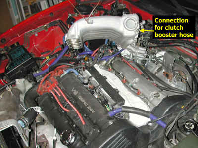
5. Clutch booster vacuum hose. Pinch the clamp and slide it down the hose an inch or so. Grasp the hose, twisting slightly if needed, and pull it off the plenum.
6. Oil supply line bracket. Remove the bolt (12 mm) holding the oil supply line near the rear turbo for more working space.
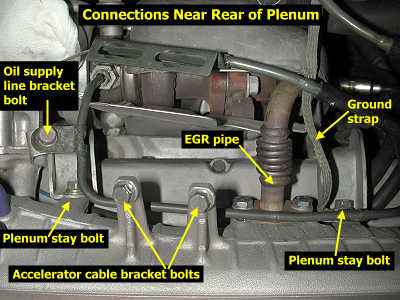
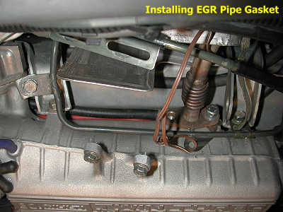
7. EGR pipe. Remove the passenger-side screw (12 or 13 mm) from the EGR pipe (it comes up from the rear cat near the oxygen sensor). Loosen (but do not remove) the driver-side EGR pipe screw, and slide the metal gasket downward (or upward). Securely attach a wire to the gasket (forceps can help with this), then remove the remaining EGR pipe screw. You may need to pry the pipe away from the plenum a little with a slotted screwdriver or similar tool. Set the gasket aside if it can be re-used. The screws are M8x1.25mm and 20 mm long (threded section below head).
8. Rear plenum stays. Carefully remove the two screws (12 mm) attaching the rear of the plenum to the stays (brackets). Note that a ground strap attaches to the driver's side stay. These screws are also M8x1.25mm and 20 mm long. The ones on my engine had captured washers and were thread cutting machine screws.
9. 3-plug bracket and fuel injector harness. Remove the two (10 mm) bolts that hold the 3-plug bracket on the passenger's side of the plenum. Remove the two (10 mm) bolts holding the fuel injector harness to the plenum.
10. Front plenum bolts/nuts. Remove the three (12 mm) bolts from the plenum front, the two long (12 mm) bolts from the plenum top, and the two (12 mm) nuts from the plenum front sides. The plenum may pop a little with the release of pressure.
11. Plenum. Lift the plenum straight up to clear the front studs then tilt toward the passenger side. Suspend the plenum from the hood using a cord. If needed, use a piece of wood to help prop the hood open. The fuel pressure regulator hose will probably slide off the throttle body, but the rest of the hoses should have enough length to move the plenum around without a problem. Cover the intake manifold with a clean rag. You definitely do NOT want anything falling in there.
12. Spark plug wires. If necessary, clean, vacuum, or blow out the plug areas and wells to remove dirt and oil. You do not want anything falling into the cylinders when the plugs are removed. Use a twisting motion to loosen the wires. Then pull the wires from the plugs. Note the routing through the brackets. The wires are of different lengths and not easily mixed up. Note that the cylinder numbers are stamped onto the coil assembly bracket.
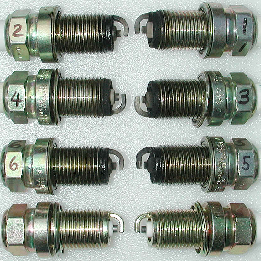
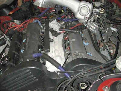
13. Spark plugs. The front plugs are easy to remove. The back ones may require moving the plenum around some. I like to note which cylinder each plug comes from for the next step. The picture below shows how our cylinders are numbered. If you are not immediately installing the new plugs, stuff a small piece of clean rag or towel into each spark plug opening.
While the plugs are out
Now is an excellent time to inspect the plugs for color, oil, damage, burns, and detonation specks (you may need a magnifying glass). This can tell you how each cylinder is performing. Be sure to compare the back plugs to the front ones for electrode wear. It is possible that the back ones were not changed the last time the front ones were. The spark plugs you see below have a few thousand miles on them and so do not show much wear. However, there are indications that the air-fuel mixture is rich and that excessive oil is entering some cylinders. These plugs are NGK BCPR6ES that have a copper alloy electrode. For information about spark plug operation and a cross-reference guide please look at my web page 2-sparkplugtech.htm. The chart on this web page 2-sparkchart.htm shows common spark plug tip conditions. Click on the image below to load a close-up view of the electrodes (image size is 830x830 pixels; file size is 113 KB).
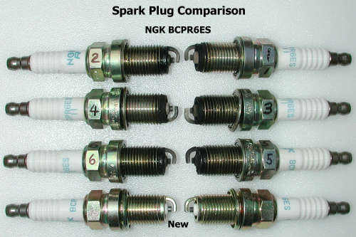
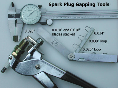
If changing or checking the gap, be careful to not damage the platinum tips. The stock gap is 1.0-1.1 mm (0.039-0.043"). The proper spark plugs are platinum NGK PFR6J-11 (or Denso PK20PR-P11 or equivalent) for the DOHC engine, and NGK BPR5ES-11 (or Denso W16EPR11 or equivalent) for the SOHC. When gapping the plugs, be sure to check the gapping tool, whether a plier type or feeler strips or loops, with a micrometer. Thousandths of an inch count when it comes to the plug gap. I use a plier-type tool to set the gap. Then I check the gap with a feeler gauge strip (sometimes two strips stacked together must be used). Finally, I use the feeler gauge loops to be sure the gap is neither too tight nor too loose. For the 0.028" I use here, the 0.025" loop easily slides into the gap and the 0.030" loop will not fit. In the picture above, only the new plugs shown have been set with this method. The old plugs were set by bending the ground electrode with a "notch" tool. Ideally, you want the ground electrode tip to be parallel to the center electrode surface.
Here are some thoughts for you if you are considering changing from precious metal tipped plugs to another type, or are considering changing the spark gap to larger or smaller than stock.
Copper-alloy plug advantage: stronger spark (requires more voltage) than platinum- or iridium-tipped plugs if all are at the same gap. This theoretically means better chances for combustion and so better power.
Copper-alloy plug disadvantage: stronger spark (requires more voltage) than platinum- or iridium-tipped plugs if all are at the same gap. This means the ignition wires, coils, and power transistor must produce more energy to fire copper-alloy plugs at say 0.036" gap than platinum- or iridium-tipped plugs at the same gap. This can mean more misfires at higher cylinder pressures and/or higher engine rpm at larger spark gaps.
Copper-alloy plug disadvantage: electrodes will wear 2 to 6 times as fast as platinum- or iridium-tipped plugs and so must be changed more often.
As far as larger spark gaps being better, much of this evidence is from older American V8 engines that have plugs off to the edge of a 2-valve head. Larger gaps, up to maybe 0.040" to 0.060", generate a larger spark kernel and after glow and so encourage more-complete initiation of combustion in these older designed V8 heads. In our 4-valve, centrally located plug heads the advantage of and need for larger spark kernels is minimized (so I have read).
The only reason for reducing spark gap is to eliminate misfires. Misfires are usually occuring because the ignition energy produced by the coils and wires is less than what is needed to produce a good spark. Smaller gaps, or smaller electrode tips (like found on platinum- and iridium-tipped plugs), require less energy to spark. So reducing gap to elminate misfires is OK up to a point. After that either the ignition must be made better (more energy) or the cause for increased spark voltage requirements must be dealt with (lower the boost).
For our engines, too large a gap, say over 0.045", should offer no performance advantage. Medium gaps, say 0.034" to 0.043", should be fairly equivalent powerwise. Use the largest gap that also produces the least amount of misfires for your setup. Small gaps, say less than 0.030", may start to hurt combustion a little and lead to poor idle (popping in the exhaust for example) and poor emissions (the spark kernel may now be too small for good initiation of combustion). Use small gaps only in extreme situations (such as the ignition system is maxed out and boost is very high).
Now is also a good time to inspect the ignition wires for wear and excessive resistance. The factory ignition wires should all measure less than 10,000 ohms resistance from terminal to terminal. Lower resistance is better. If you are replacing the wires also, note the following arrangements. The cylinders are numbered from the driver-side (timing belt side) of the engine as 1, 3, and 5 for the front bank, and 2, 4, and 6 for the rear bank. The connections to the ignition coil use the following order, from the front of the car, 6, 3, 2, 5, 4, and 1 (these numbers are stamped on the coil bracket). There are three coils with the following cylinder pairs firing at the same time 1-4, 2-5, 3-6. Firing order is 1, 2, 3, 4, 5, 6. Note that the cylinders numbers are stamped on the coil mounting bracket indicating where the spark plug wires attach.
If you are replacing the wires, consider the MSD Ignition 8.5mm Super Conductor Wire Set (part number 31199). More information regarding these wires is on my web page 2-msd-ignwires.htm.
Installation
1. Spark plugs. Install the plugs and tighten to 25 N-m (18 ft-lb or 216 in-lb) torque. Tip: barely slide the plug into the socket just enough so that it won't fall out. Gently insert the plug and tighten a little by hand. Then remove the socket, the rubber insert should still be in it. After all plugs are started, remove the rubber insert from the socket and complete the tightening process, first by hand, then with a torque wrench.
2. Spark plug wires. Securely re-attach the plug wires noting the proper routing. In addition, check each fuel injector wiring harness connection for proper fit.
3. Manifold-plenum gasket. Remove the rag covering the manifold. Clean the surfaces of the manifold and plenum with an engine cleaner or degreaser and then wipe dry with a clean cloth. Install the new plenum gasket or the old one that has been cleaned and is free of oil an dirt. The protrusion goes to front, driver's side of the manifold. Remove the cord and lower the plenum onto the manifold studs. Do NOT attach bolts or nuts at this time. You will need the plenum loose for the next step.
4. Rear stays. Bolt the plenum to the rear two stays first. You may need to apply your weight or tap the plenum with your fist or rubber mallet to get the holes to line up. I sometimes get up on the engine with my knees on the plenum (using a rag or kneeling pad) to apply pressure. Be sure to re-attach the grounding cable and oil pipe bracket with the driver-side stay. Insert the two bolts by hand. Be sure you can turn the bolts several revolutions by hand to avoid stripping the soft aluminum threads. Torque to 18 N-m (13 ft-lbs).
5. EGR pipe. With a wire attached to the new EGR pipe gasket, insert the driver-side bolt through the EGR pipe and gasket and into the plenum. Tighten a little by hand. Remove the wire, slide the gasket around, and insert the other bolt. The bolts can now be tightened (18 N-m; 13 ft-lbs). Again, I sometimes find it easier to do this up on the engine with my knees on the plenum.
6. Oil supply line bracket. Start the bolt by hand several turns then finish with a socket and ratchet.
7. Clutch booster vacuum hose. Slide the hose onto the plenum nipple and slide the clamp to the end of the hose.
8. Accelerator cable bracket. Re-attach the bracket. Adjust the tension on the cable so that the throttle plate is closed completely (same for the dashpot) and with very little extra slack in the cable. The engine control module sets the engine idle speed using the idle speed control (ISC) stepper motor, so the throttle cable must not be applying torque (rotating force) to the throttle plate. However, too-loose a cable will result in delayed throttle response and the throttle plate may not open completely.
9. Front plenum bolts/nuts. Install the front five plenum bolts and two nuts. Torque them all to 18 N-m (13 ft-lbs). As always, start the bolts by hand several turns to minimize the chances for stripping the threads.
10. 3-plug bracket and fuel injector harness. Re-attach these components. Be sure to check the fuel pressure regulator hose and the other vacuum hoses.
11. IC pipe. Remove the rags from the top of the rear turbo and the IC pipe. After applying a small amount of high-temperature grease to the o-ring, install the rear IC pipe.
12. Y-pipe. Re-connect the Y-pipe to the throttle body. Perform another inspection of the vacuum hoses. Bolt the throttle body to its stay if you want.
13. Battery. Re-attach the negative battery cable to the battery. The disconnected battery will reset the ECM. Let the car idle a few minutes and check for leaks or other problems.
Page last updated June 26, 2006.