Alternator Rebuild
for 1991-1995 DOHC Mitsubishi 3000GT and Dodge Stealth
by Jeff Lucius
Introduction
The alternator is a component you may need to replace once or twice during the life of an engine. Prices for new or rebuilt alternators range from about $250 (auto parts stores) to as much as $400 or more (dealerships). If you decide that you want to rebuild your alternator, then this web page will provide some tips that supplement the information in the service manual and a source for some components. My web page 2-alternator.htm provides instructions for how to remove and replace the alternator.
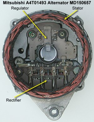
The two electrical components you want to replace inside the alternator are the voltage regulator and the diode rectifier bridge. The rectifier turns the 3 phase alternating current produced by the stator and rotor into something that resembles direct current (DC). The regulator makes the voltage of that direct current stay within reasonable bounds, usually in the range of 12.6 to 14.5 volts. The battery helps to smooth out the "ripples" in the DC charging current produced by the alternator, as well as provides the emf (electromotive force) that resists the current flow from the alternator and therefore controls alternator output current (amps). The alternator for the 1991-1995 DOHC 3S models has a rated DC current output of 110 amps.
There are also brushes that can be replaced if the regulator and rectifier are in good shape. Mechanically there are two bearings that support the rotor that are replaceable. Mitsubishi also lists the rotor and stator as replaceable parts, though it should be rare for these two parts to ever need replacement.
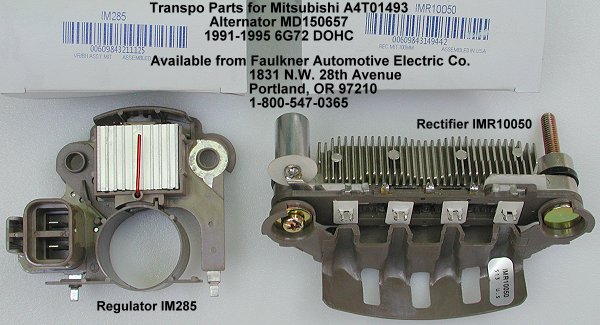
I quickly found that the price of the regulator and rectifier from a dealer could equal or exceed the cost of a new or rebuilt alternator ($236-300 with core charge). Jeff Crabtree provided an aftermarket source for these parts on the Team3S email list: Transpo Electronics, Inc. at http://www.transpo.de/ and http://www.transpo-usa.com/. I called Transpo and they referred me to one of their retail distributors, Faulkner Automotive Electric Co., that will ship anywhere in the USA. You can call Transpo USA (Orlando, FL, 800-872-6776 or 407-298-4563) or visit their web site to get contact information for other retail distributors. I found Faulkner Automotive Electric to be very helpful, plus they shipped the parts quickly.
Faulkner Automotive Electric Co.
1831 N.W. 28th Avenue
Portland, OR 97210
phone: 503-227-3567; 800-547-0361
The table below shows the list and discount prices from Norco Mitsubishi and the prices I paid from Faulkner. Shipping from Oregon to Colorado came to $5.89 for the regulator and rectifier (the parts arrived within days of the phone order). The regulator includes new brushes. By the way, Mitsubishi has discontinued providing brushes. The one Denver area rebuild shop I found that carried these brushes wanted $20 --- a brush. Absurd! Even with shipping they are much cheaper from Faulkner. Alternator part number MD197470 is the replacement part for all 1991-1995 DOHC 3000GT and Stealth. You can call Faulkner for prices and availability for other parts for this alternator and for the 1996-1997 alternator (MD324754) and the 1998-1999 alternator (MD354815). Faulkner also carries bearings for these alternators; I didn't ask the price.
| Selected Components for the A4T01493 Mitsubishi Alternator |
| Part Name |
Part Number |
List Price |
Discount Price |
Faulkner Price |
Transpo Part Number |
| Alternator |
MD197470 |
$328.45 |
$279.18 |
NA |
NA |
| Regulator |
MD611743 |
$181.42 |
$145.14 |
$40.28 |
IM285 |
| Rectifier |
MD611742 |
$95.98 |
$76.78 |
$34.48 |
IMR10050 |
| Brushes |
MD611689 |
$4.38 |
$3.50 |
$2.31 |
38-8305 |
For comparison, a brief internet search in April 2004 found the following discount prices for rebuilt or new 110-A alternators for our cars (1991-1995 DOHC models).
At RockAuto.com:
- World Wide Part # 14973 - $156.79 plus $80 core charge ($236.79)
- Bosch Part # AL4009X - $164.89 plus $83 core charge ($247.89)
- AC Delco Part # 3211233 - $226.79 plus $55 core charge ($281.79)
At www2.maximumautoparts.com:
- Product number F4000-27366 (Bosch) - $161.70 plus $75 core charge ($236.70)
- Product number F4000-130034 (Denso) - $264.64 plus $34 core charge ($298.64)
Assuming you have the alternator still in its bracket on your workbench, you'll need the following tools to disassemble the alternator and replace the regulator and rectifier: 8-mm and 12-mm sockets and wrench, 2 small slotted screwdrivers with 3/16" or smaller blades, #2 Phillips screwdriver, #0 Phillips screwdriver, needle nose pliers or hemostats, a soldering iron that reaches at least 700ºF, rosin core solder, electrical parts cleaner (such as CRC Lectra-Motive), and safety glasses (for when you are separating the two halves of the alternator). Please read all of this web page before beginning this procedure.
The Reason I Rebuilt the Alternator
I noticed when datalogging my car that system voltage would decrease to about 13 volts or slightly less during wide-open throttle (WOT) acceleration [VOM measurements at the battery confirm the datalogger values]. It is to be expected that system voltage might decrease some during the heaviest load on the engine. However, 13 volts seemed a little low. I suspected the alternator. I measured voltage during various engine operating conditions before and after the alternator rebuild. The table below summarizes the results. Ambient conditions were dry summer mornings in Colorado with air temperature between 70º and 80º F. "Warm idle" was immediately after the engine was run for 30 minutes with a combination of street and highway driving. "Cruising" and "WOT" were recorded during that 30 minutes of driving. The "Range for Others" values were collected from responses from 11 other 3S owners (1991-1996 VR4/TT models) on the www.3si.org message board.
| System Voltage Comparison |
| Engine operation |
Before rebuild |
After rebuild |
Range for Others |
| Cold start |
14.2 |
14.44 |
14.0-14.5 |
| Warm idle |
13.3-13.4 |
13.5-13.6 |
13.4-13.8 |
| Cruising ~3000 rpm |
~13.46 |
~13.8 |
13.7-13.9 |
| WOT 15.5 psi boost |
12.95-13.02 |
13.22-13.34 |
12.7-13.8 |
Well the rebuild did not result in the 0.5+ volt increase I was hoping for. Still, 0.2 to 0.3 volt increase under all operating conditions is an improvement. I was hoping to have system voltage at 13.5 volts or more during WOT for maximum performance from the ignition system and fuel pump, and at 14.0+ volts during cruising and warm idle for best charging of my sealed lead acid battery. Nevertheless, my voltages after the rebuild seem typical from the limited responses I got on the 3SI message board. Part of the problem may be the relatively high temperatures encountered in our engine bay, not so much air temperatures but temperatures of the engine metal parts and components attached to the engine. All alternator regulators are voltage compensated to provide higher voltage when the regulator is cold and lower voltage when the regulator is warm. The Regulating Voltage Table below is from the 1992 service manual. The voltages I am getting after the rebuild are on the low side of the listed ranges. I'll need to check the wiring (especially the grounding cables) for possible sources of resistance or other voltage loss, and monitor the alternator "B" cable for current under different loads using a DSO (digital storage oscilloscope).
| 3000GT/Stealth Alternator |
| Temperature |
Regulated Voltage |
| -20ºC (-4ºF) |
14.2-15.4 |
| 20ºC (68ºF) |
13.9-14.9 |
| 60ºC (140ºF) |
13.4-14.6 |
| 80ºC (176ºF) |
13.1-14.5 |
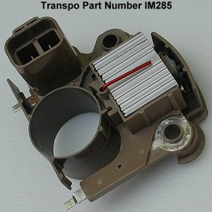
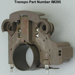
Transpo Regulator and Rectifier
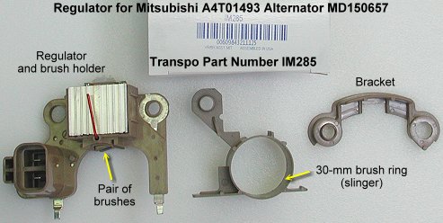
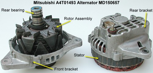
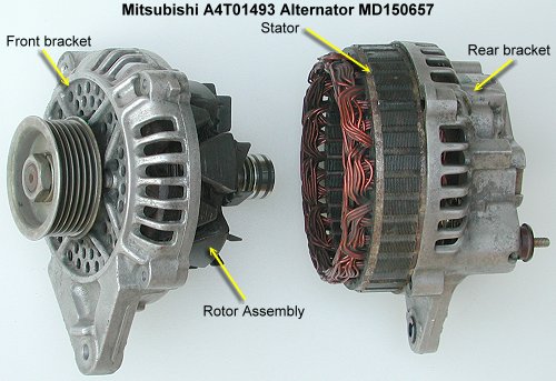
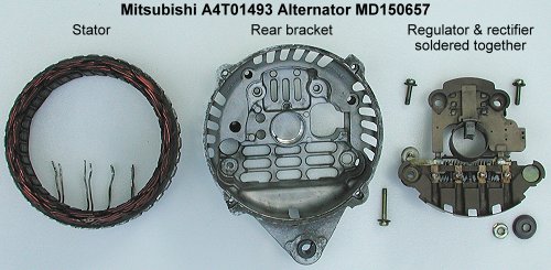
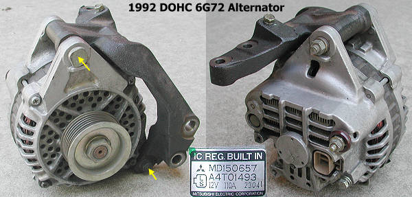
The Transpo web site lists the wrong regulator for our alternator. It says to use part number IM280. IM280 will not work; the brush ring is too small at 26 mm and the size of the part is too small, the tabs for Trio and B+ are too short to reach the posts on the rectifier. Part number IM285 is the correct regulator for our alternator. IM285 consists of three pieces as shown below. The rectifier is one piece plus a loose fastener. When ordering parts, talk to the salesperson at Faulkner (or other Transpo distributor) and describe what alternator you have so that they can find the correct parts. The label on the alternator has the Mitsubishi model number on it. For our cars (1991-1995) the model is A4T01493 (see picture at the end of this web page).
Disassembly
1. Remove bracket. If the bracket is still on the alternator after having removed the alternator from the engine, remove the bolts attaching the bracket and force the alternator out of the bracket.
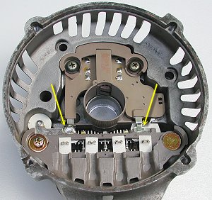
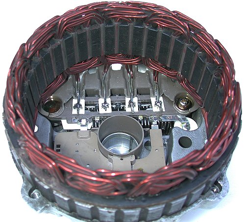
2. Separate stator and rotor. Remove the four 8-mm bolts that hold the front and rear bracket assemblies together. The rotor is attached to the front bracket and the stator is attached to the rear bracket. Use two small slotted screwdrivers to pry apart the front bracket and stator core. Note that after you removed the 4 bolts there is an opening at the edge of the front bracket near the 4 fastening points that will let you get the screwdriver under the stator core and pry against it. Do not insert the screwdriver very deep because you might damage the stator wiring. Insert the screwdriver just enough to catch the lip of the stator core (the "solid" piece that holds the front and rear bracket apart after assembly; see arrows in pictures below). Move the screwdrivers to different combinations of the 4 pry points to slowly force the stator evenly off the rotor. You might want to wear safety glasses to protect your eyes from small pieces of metal or coating that might break off.
3. Clean parts. At this point, after the two brackets are apart, I like to clean oil, grime, and dust off everything I can get to. Electrical parts cleaner and rags should do the job. The pictures below were taken after I cleaned the parts.
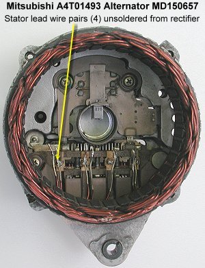
4. Unsolder the stator wires. Pre-heat your soldering iron to its highest temperature. With pair of pliers exert mild upward force of one pair of stator wires as you apply heat from the soldering iron. If after 30-60 seconds the factory solder does not melt, touch some fresh solder to the junction of your iron and the stator wire solder. This will help spread the heat from your iron. The stator wire solder should then melt enough to pull the wire pair loose. Repeat for the other 3 wire pairs.
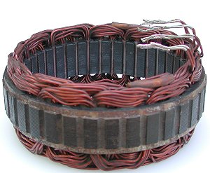
5. Remove stator. With the wires leads unsoldered from the rectifier, remove the stator from the rear bracket. Clean the solder off the wires with your iron. You want to be careful when handling the stator so that the insulating coating on the coil wires is not scraped or chipped off.
6. Remove regulator and rectifier. On the outside of the bracket, remove the 12-mm nut and insulator on the B+ post of the rectifier. Inside the bracket remove the three Phillips screws that attach the regulator and rectifier. The two components are removed together because they are still soldered together. Save the screws, insulator, and nut for the assembly steps.
7. Clean rear bracket. Clean dust and oil off the inside of the rear bracket.
8. Inspection. The service manual describes several tests you can perform to check for problems with the rotor and stator. Basically, you are checking for continuity or lack of continuity between various components. Replace if there is a problem.
9. Brush replacement. If you want to just replace the brushes and re-use the regulator, take the bracket and slinger off the regulator. There is a plastic cap on the top of the regulator,opposite from where the brushes protrude. Unsolder the brush braided wires from the terminals there. Remove the brushes and springs. Slide the new brush wires through the springs and insert the combination into the holder. Solder the brush wires back to the terminals. Replace the plastic cap.
Assembly
1. Remove rubber stopper. Using a #0 Phillips screwdriver and working from the inside of the rear bracket, press the rubber stopper out of the bracket and save. This hole is used to insert a wire to hold the brushes in the regulator during assembly of the rotor and stator.
2. Rectifier. Fasten the rectifier into the rear bracket. Tighten the Phillips screw. On the outside of the bracket, slide the insulator onto the B+ post and add the nut. Tighten the nut. Remove any small stickers from the rectifier if still present.
3. Regulator. Assemble the three regulator pieces as shown below and remove the wire. Save the wire. Be sure the small plastic cover is still in place insulating the ends of the brush wires and that the brush wires are in their little channels molded into the regulator. I had to trim the little nubs on the plastic piece that protects the brush wires with a utility knife for the regulator to fit properly. The nubs were forcing the bracket on the regulator assembly to sit "too high" and the bracket would not fit properly into the main body of the regulator. The picture below on the right shows this. Insert the regulator assembly into the rear bracket. There are guides in the bracket to align the regulator. Fasten the regulator in with the two Phillips screws and tighten the screws. You should not have to force anything into place except maybe the two metal tabs into the posts on the rectifier.
4. Solder regulator to the rectifier. Be sure the regulator is aligned correctly. In particular, be sure the slinger is centered over the opening for the bearing in the rear bracket. Solder the two tabs of the regulator to the posts on the rectifier. In the picture below, only the left slot is soldered. The picture also shows that I have re-inserted the wire to hold the brushes up, but this is not necessary yet.
5. Solder stator wires to rectifier. Note the channels in the rectifier to insulate the stator wires from the rear bracket. The wires must fit firmly into these channels so that they do not rub against the rotor. Clean the extra solder off the stator wires. This should still leave them tinned. Bend them as shown below and practice fitting the stator into the rear bracket to be sure the wires are bent properly and fit tightly against the channels in the rectifier and between the posts on the rectifier. The ends of each wire pair should not extend past the end of the white insulating pad surrounding the posts. Solder the stator wire pairs to the rectifier posts. I used hemostats to hold the pairs in place as I soldered.
6. Re-assemble the alternator "halves". Push the brushes up into the regulator and insert the wire from the outside of the rear bracket through the holes in the brushes to hold them in place. Slowly start to slide the two halves together, front bracket/rotor and rear bracket/stator. Carefully work the rear bearing past the brushes and into place in the rear bracket. You may have to wiggle the rotor a little. The rear bracket assembly will rotate easily until the stator contacts the front bracket. Align the front and rear brackets in their proper positions and slide the stator a little into the front bracket. Continue sliding the stator into the front bracket. When the two pieces are maybe 1/8" apart, insert the four 8-mm bolts and be sure you can thread them each a few turns by hand. Now finish pressing the stator into the front bracket. I used my upper body weight to press down on the rear bracket while the pulley rested on the workbench. After the parts are together rotate the pulley to be sure the rotor is not contacting the stator wires. If you hear a ching, ching, ching as the pulley rotates, disassemble the alternator and reposition the stator wires. Tighten the four 8-mm bolts. Remove the wire holding the brushes back and insert the rubber stopper. I was unable to get the rubber stopper completely inserted into the rear bracket. Put the bracket back on the alternator and install in the car (see 2-alternator.htm).
In the left picture below, the top bolt that fastens the alternator to the bracket is installed reverse of what it should be.
Measure charging voltage after the installation is complete.
Page last updated September 5, 2004.