Alternator Removal
in the DOHC Mitsubishi 3000GT/Dodge Stealth
by Jeff Lucius
Introduction
These instructions supplement the instructions in the service manual for removing the alternator from the DOHC Mitsubishi 3000GT and Dodge Stealth. The tools and supplies required are a hydraulic jack, jack stands, two wheel chucks (blocks of wood are fine), lug wrench or the appropriate socket and ratchet for your wheels, a torque wrench that goes up to 100 ft-lbs, a small flat-head tool for some Stealth owners to remove the wheel center cap, 10-mm, 12-mm, 14-mm, and 12-mm-deep sockets and ratchet (a swivel head ratchet may be required), 3" and 6" socket extensions, 2' to 3' breaker bar, six feet of cord, and safety glasses (for working under the car). Please read through all the instructions before starting this procedure. The work below was performed on a 1992 Dodge Stealth R/T Twin Turbo with custom intercooler piping.
Removal
1. Disconnect negative battery cable. With the ignition off, remove the negative battery cable from the battery. Be sure you have security codes for any devices that might need them before you do this.
2. Lift and support car, remove wheel. You must remove the driver's side front wheel to gain access to the alternator drive belt tensioner. I have some tips for lifting and supporting the car at my web page 2-raisecar.htm and removing the wheel at my web page 2-tirerotation.htm. Generally, you want to loosen the wheel lug nuts a little, lift the car, finish removing the wheel, and rest the front cross member near the rear of the control arm on a jack stand. Be sure the car is securely and safely supported before you proceed.
3. Front splash shield. Remove the tapping screws, 10-mm bolts, and clips with screws from the plastic splash shield in front of the wheel well. The clips with screws are removed by uncsrewing the screw part a little then pulling the whole clip out. If the screw does not want to back out, then try putting a little upward pressure by lightly prying around the base of the screw with a small screwdriver or thin knife blade.
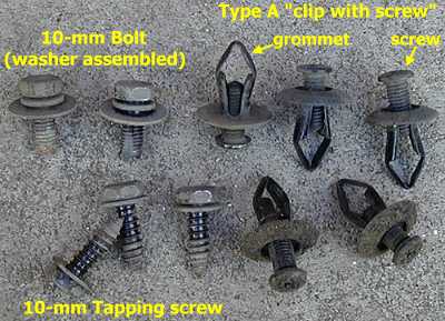
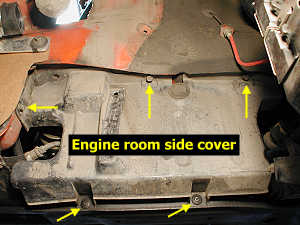
4. Engine room side cover. This cover is behind the driver's side front wheel and conceals the belts and pulleys. Remove the two clips with screws on the bottom and the three 12-mm bolts near the top of the side cover. Set the side cover out of the way.
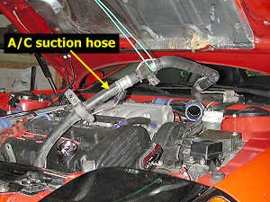
5. A/C suction line. Remove the two 10-mm nuts toward the back, the 12-mm nut on the side, and the 12-mm bolt at the front of the air conditioning suction hose. Lift the hose until it no longer moves easily and tie it off to the hood using a cord.
6. I/C pipes. I have aftermarket intercooler pipes and removed enough of the pipes to make access easy to all parts I needed to get to. If you have the stock I/C pipes, remove the pieces as shown in the illustration above from the service manual. Block the openings in the remaining I/C pipes with rags to prevent objects from entering.
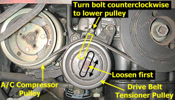
7. Tensioner pulley and drive belt. Before adjusting the tensioner, take a moment to note the tension on the belt between the idler and crankshaft pulleys as shown in the figure at the end of the web page. Loosen, but do not remove, the 14-mm bolt in the center of the tensioner pulley. With a 12-mm socket, rotate the tensioner bolt counterclockwise to lower the pulley and reduce tension on the belt. Stop when the belt is loose enough to remove. If you plan to re-use the drive belt, then mark the outer edge of the back of the belt (flat side) with chalk so that you can re-install it the same orientation. Remove the belt and inspect it; replace if old (every 30,000 miles or 3 to 4 years) or if it shows signs of wear. Note how the ridges in the belt fit in the grooves of the different pulleys.
8. A/C condenser fan assembly. The service manual does not mention removing this fan assembly, but you need the extra room when removing and installing the alternator, at least when the bracket is still attached. Some owners have removed the alternator without removing this fan, but I could not figure how to do it. Perhaps if the alternator is also removed from its bracket before attempting to squeeze it out of the engine bay. Mark the two electrical connectors with masking tape next to the condensor fan (the one near the alternator) so you know which goes where (actually, the two connectors are slightly different). Disconnect the two connectors by pressing on the levers and pulling up. Remove the four 10-mm bolts on the fan assembly. For the two bottom fasteners you may need to remove some undercovers or active aero components; a 10-mm socket with several extensions may also work. Pull the assembly out through the top. The upper mounting "brackets" on the radiator for this fan have sharp corners which could benefit from filing at the edges.
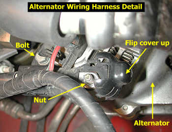
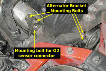
9. Wiring harness connections and brackets. Grasp the bottom of the rounded plastic cover that protects the top cable connection (positive "B" terminal) and raise the cover. Remove the upper 10-mm nut and lower 10-mm bolt, and pull the harness away from the alternator a little. Disconnect the harness completely from the alternator by pressing on the connector lever and pulling the connector away from the alternator. Identify the bolt that attaches the oxygen sensor connector to the alternator bracket and remove the bolt and oxygen sensor connector bracket.
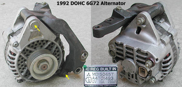
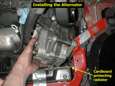
10. Alternator bracket. Protect the radiator near the alternator with a piece of carboard (I used some duct tape to secure the cardboard; that blue masking tape painters use will not harm your paint). Remove the two 14-mm bolts on the driver's side of the bracket (the longer one goes on the bottom). Loosen both 12-mm upper bolts but remove only one. Now support the alternator with one hand as you remove the other bolt. Maneuver the alternator in its bracket up through the top. Two bolts secure the alternator to its bracket. In the lower left picture below, the top bolt that fastens the alternator to the bracket is installed reverse of what it should be. The lowest bolt shown the same picture (yellow arrows) is the one that may be hard to remove to separate the alternator from its bracket in the engine bay (to remove the alternator without removing the condensor fan).
Rebuilding
Tips for replacing the voltage regulator and rectifier in the alternator are on my web page 2-alt-rebuild.htm.
Installation
Installation is basically the removal procedures performed in reverse order. Protect the radiator fins with some cardboard. Tape the condensor fan electrical connectors out of the way. The picture below shows the correct orientation to fit the alternator through the space available.
If you are re-using the drive belt, be sure to install it in the same orientation as it had before removal (same side facing the wheel well). Insert the belt from above. Turn it "sideways" to fit it in between the alternator pulley and the AC pipe. Correctly tension the drive belt using its tensioner pulley. Before installing the plastic covers and wheel, temporarily install the IC pipes and battery negative cable and start the engine to check the belt operation. Be sure to also start the AC compressor to put some extra load on the belt. If the belt squeals it is either misaligned or too loose. I found that my old belt squealed when installed "backwards" from how it was removed. It did not squeal when installed in the same orientation. If you have messed with both drive belts, spray a little water on one belt at a time to see which is squealing. A misalligned belt will stop squealing for a very short time after water is sprayed on it, but the squealing quickly comes back louder than before. If the belt is loose, the squealing will immediately get louder. Also note that there is just a little play in how the alternator bolts in. If misalignment is a problem, loosen all four bracket mounting bolts (this may require again removing an IC pipe), reposition the alternator, and tighten the bolts to see if this helps. Do not tighten the belt too much because this can lead to shaft bearing failure over time.
Here are some links concerning drive belt adjustment.
http://www.gates.com/brochure.cfm?brochure=1026
http://www.ridgeap.com/tips/the_charging_system1_2.htm
http://www.utfleets.com/library/features/accessory_drive_belts.htm
After you are satisfied the drive belt is installed correctly, disconnect the battery negative cable and re-install the other parts. Tips for mounting the wheel are on my web page 2-tirerotation.htm. The last thing to do is re-connect the negative battery cable.
Page last updated August 22, 2004.